Lighting device

a technology of lighting device and resin material, which is applied in the direction of semiconductor devices for light sources, lighting and heating apparatus, fixed installations, etc., can solve the problems of increasing the cost of material, affecting the entire cost of manufacturing the lighting device, and requiring a large so as to improve decoration, reduce the required amount of resin material, and improve the appearance of the lighting device.

Inactive Publication Date: 2009-03-24
STANLEY ELECTRIC CO LTD
View PDF3 Cites 8 Cited by
  • Summary
  • Abstract
  • Description
  • Claims
  • Application Information

AI Technical Summary

Benefits of technology

[0017]According to the disclosed subject matter, when viewed from different observation positions, one can see the light source as if it is displaced or deformed so that variation in appearance of the lighting device can be achieved with improved decoration. Since the adopted inner and / or outer lenses may be formed from a thin plate material, the required amount of resin material can be reduced and any shrink problem during resin-molding may be prevented. Furthermore, the lenses can be formed by a common manufacturing method such as injection molding, resulting in a reduced manufacturing cost.

Problems solved by technology

Therefore, a substantial amount of resin material is required.
The resin material for use in this lighting device application is required to have a particular transparency, durability, water-resistance, and the like, which increases the material cost.
This affects the entire cost for manufacturing the lighting device.
Accordingly, it is difficult to provide special effects such as a light source displacement effect wherein one can see the light source as if it is displaced at different observation positions.
This means it has a monotonous appearance and is not decorative.

Method used


Image

  • Lighting device
  • Lighting device
  • Lighting device

Examples


Embodiment Construction

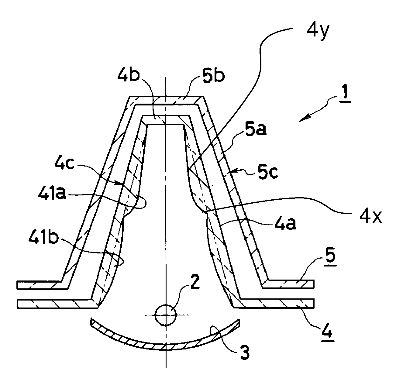
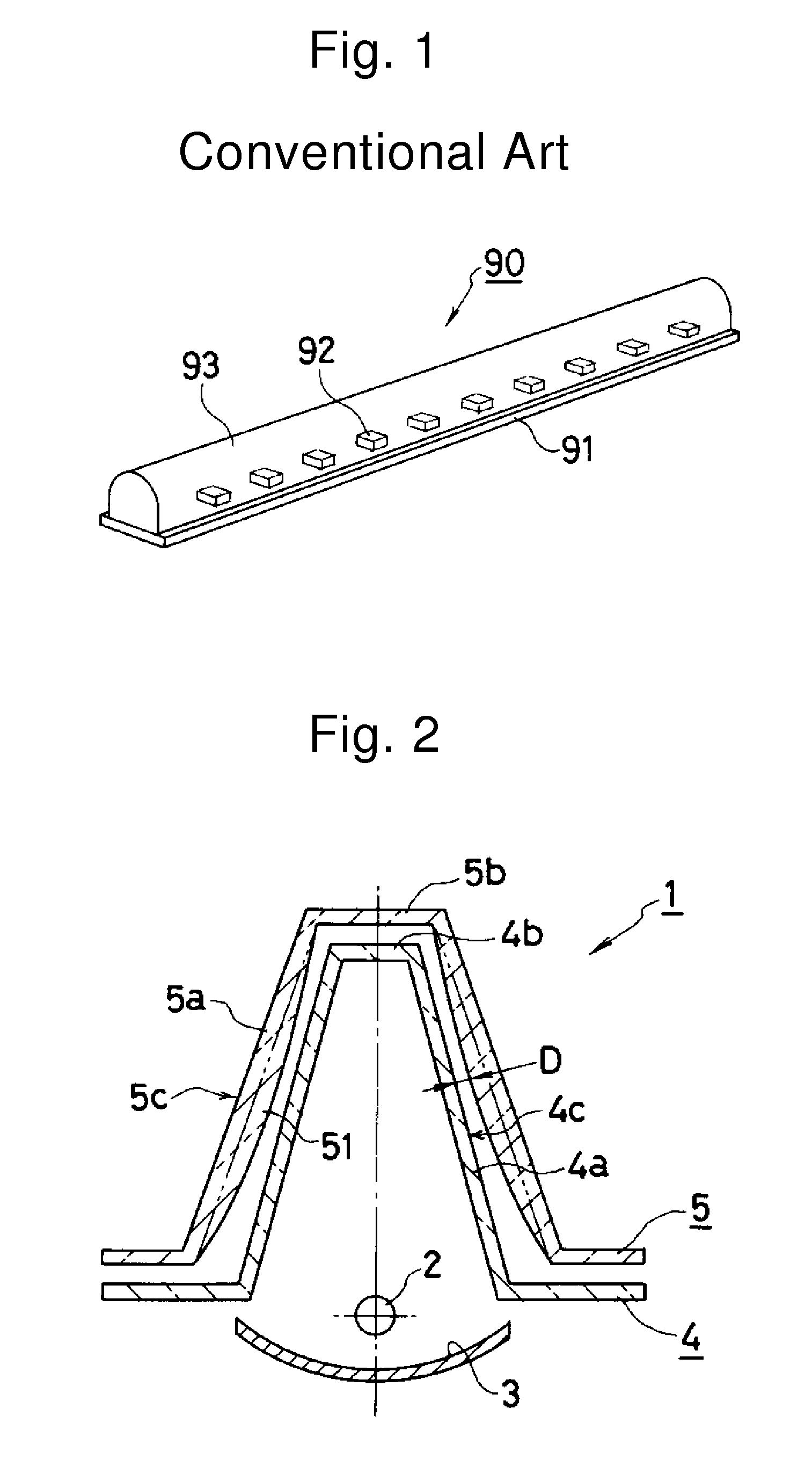
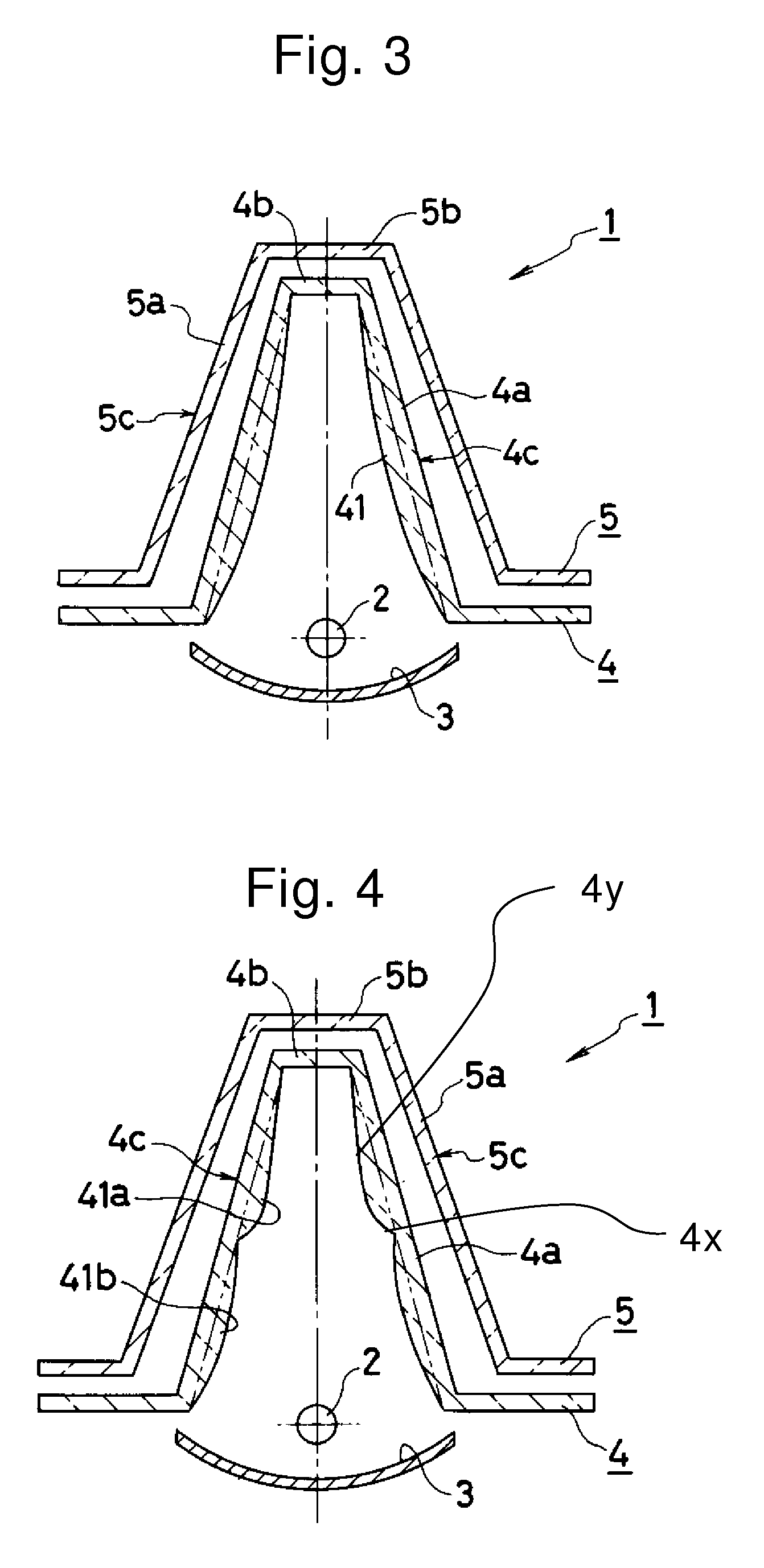
[0026]Hereinafter, a description will be given of exemplary embodiments of lighting devices made in accordance with principles of the presently disclosed subject matter. In FIG. 2, the reference numeral 1 denotes a lighting device made in accordance with principles of the disclosed subject matter. The lighting device 1 is configured to include a light source 2, a reflector 3, an inner lens 4, and an outer lens 5. Examples of the light source 2 can include an LED chip, a cold cathode discharge tube, and the like. The reflector 3 can reflect the light emitted from the light source 2 to direct the light to a desired direction, for example, upward in the illustrated example. The inner lens 4 is provided in an illumination direction of light from the reflector 3 and can be formed by bending or otherwise shaping a transparent plate member into a shape in which a cross section shows a trapezoid with a projecting part 4a. The outer lens 5 is provided in front of the inner lens 4 with an app...


PUM


Abstract

A lighting device can include a light source in line and a reflector behind the light source. In front of the light source, a transparent inner lens and a transparent outer lens can be provided with a gap formed therebetween. The shape of the lens can be defined by bending a plate member so as to have a projection portion that surrounds or opens towards the light source. The inner lens and the outer lens can each have a flat part at a position opposite the light source and in the illumination direction. When observed from different positions, the light source can appear as if it is displaced or deformed.

Description

[0001]This application claims the priority benefit under 35 U.S.C. § 119 of Japanese Patent Application No. 2006-052381 filed on Feb. 28, 2006, which is hereby incorporated in its entirety by reference.BACKGROUND[0002]1. Field[0003]The disclosed subject matter relates to a lighting device for use in a vehicle light such as a stop lamp, an illumination lamp for interior illumination, and the like. In particular, the disclosed subject matter relates to a lighting device with lighter weight and improved outer appearance.[0004]2. Description of the Related Art[0005]FIG. 1 shows a conventional exemplary configuration of a lighting device 90 of this type. The lighting device 90 can include a substrate 91, LED chips 92 mounted on the substrate 91, and a transparent resin part 93 which covers the chips 92. The substrate 91 is formed of a conductive material such as a metal material having superior heat conductivity. The substrate 91 may be rectangular. The plurality of LED chips 92 is mount...

Claims


Application Information

Patent Timeline
Patent Type & Authority Patents(United States)
IPC IPC(8): F21V5/00
CPCF21S48/215F21S48/2212F21V5/04F21W2101/14F21V5/008F21V7/06F21V13/02F21Y2101/02F21Y2115/10F21S43/14F21S43/26F21W2103/35F21W2103/00
Inventor UCHIDA, DAISUKEKONDO, TOSHIYUKI
Owner STANLEY ELECTRIC CO LTD
Why Eureka
Try Eureka