Optical connector component and optical connector using the same

a technology of optical connectors and components, applied in the field of optical connector components and optical connectors, can solve the problems of complex manufacturing process for including short-length optical fibers in optical connectors, cost increase, cost increase, etc., and achieve the effect of facilitating fusion-splicing operation and short tim

Active Publication Date: 2009-03-24
SEIKOH GIKEN
View PDF4 Cites 27 Cited by
  • Summary
  • Abstract
  • Description
  • Claims
  • Application Information

AI Technical Summary

Benefits of technology

[0010]The present invention has been achieved in view of the above circumstances, and an object of the present invention is to provide an optical connector component capable of easily performing a fusion-splicing operation on a fusion-spliced optical connector at an actual site in a short time, without need to perform additional special operations, and to provide an optical connector using the optical connector component.

Problems solved by technology

However, the mechanically-spliced optical connector has disadvantages in that a manufacturing process for including the short-length optical fiber in the optical connector is complicated and cost increases.
Furthermore, because of presence of optical connectors of many types different in the shape of the housing, it is necessary to prepare accurate mechanical splice members of shapes corresponding to the respective optical connectors, disadvantageously resulting in cost increase.
Due to this, it is undesirable to increase such special operations to be performed at the actual site.

Method used


Image

  • Optical connector component and optical connector using the same
  • Optical connector component and optical connector using the same
  • Optical connector component and optical connector using the same

Examples


Embodiment Construction

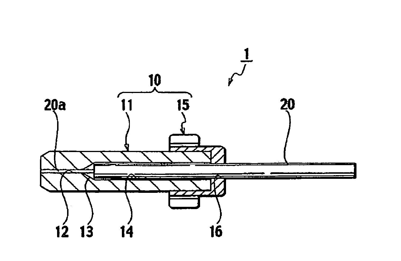
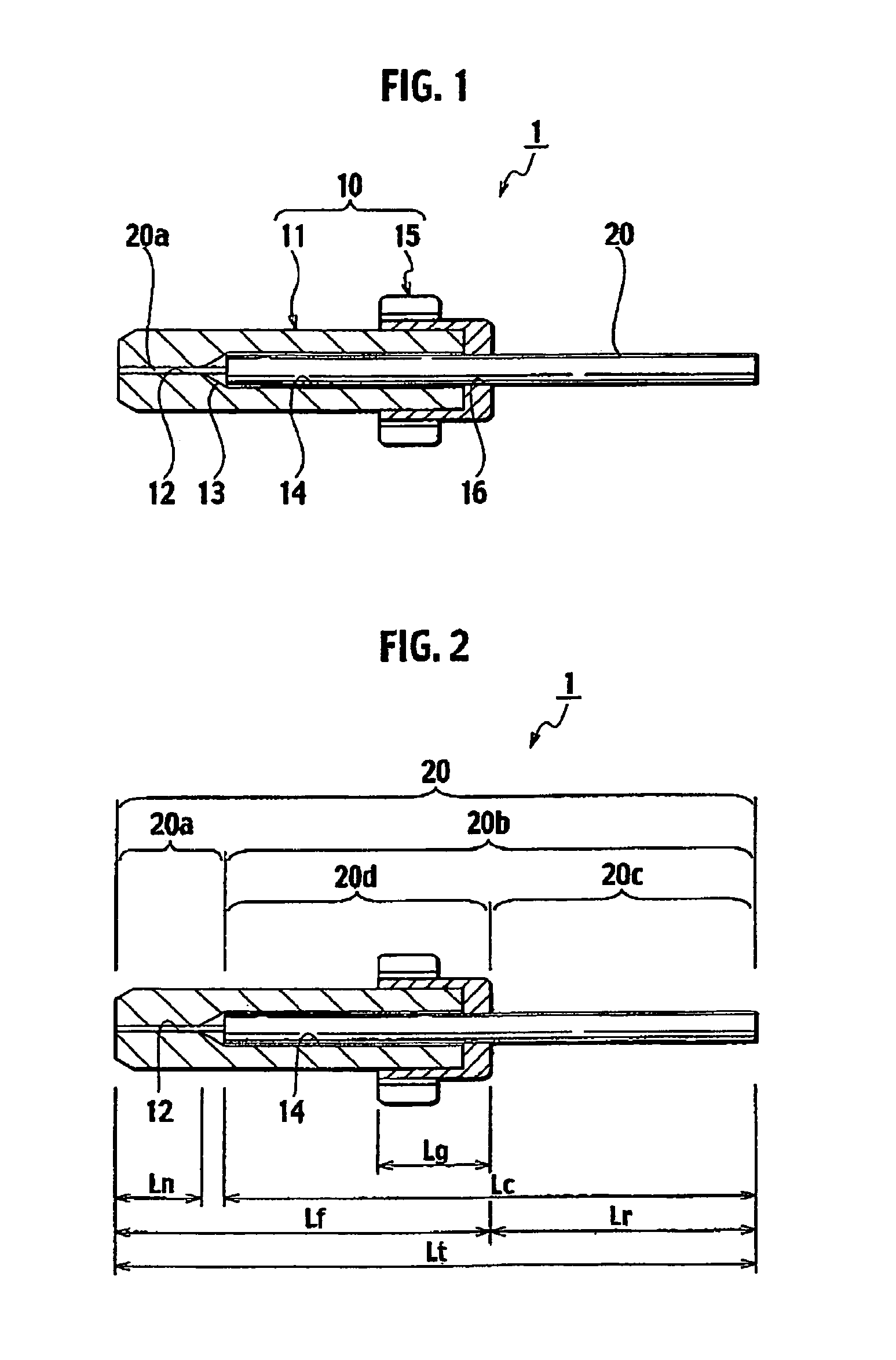
[0031]FIGS. 1 and 2 are cross-sectional views showing an embodiment of an optical connector component according to the present invention. An optical connector component 1 is configured such that a short-length optical fiber 20 is attached to a ferrule 10. The ferrule 10 includes a capillary 11 and a flange 15 that holds a rear end of the capillary 11. The short-length optical fiber 20 includes a bare optical fiber portion 20a formed on its tip end, which any coating around the bare optical fiber portion 20a being removed.

[0032]A minute through hole 12 is formed in the capillary 11 to be stored therein the bare optical fiber portion 20a of the short-length optical fiber 20. A coated-portion storage hole 14 is also formed in the capillary 11 to be stored therein a part of a coated optical fiber portion 20b (see FIG. 2) continuous to the bare optical fiber portion 20a. The minute through hole 12 and the coated-portion storage hole 14 are formed in this order from a tip end (a left end ...


PUM


Abstract

To provide a fusion-spliced optical connector capable of easily performing a fusion-splicing operation at an actual site in a short time, without need to perform additional special operations. An optical connector component is configured to attach a short-length optical fiber to a ferrule including a capillary and a flange. The capillary comprises a minute through hole and a coated-portion storage hole formed in the capillary, the minute through hole to be stored therein the bare optical fiber portion of the short-length optical fiber and the coated-portion storage hole to be stored therein a part of a coated optical fiber portion of the short-length optical fiber continuous to the bare optical fiber portion. The flange includes a coated-portion penetrating hole formed in the flange to be penetrated therein a very short portion continuous to the part of the coated optical fiber portion stored in the coated-portion storage hole. The short-length optical fiber extends rearward from the coated-portion penetrating hole of the flange by a length of a required extra-length splice portion when the bare optical fiber portion is fixedly stored in the minute through hole of the capillary and the part of the coated optical fiber portion continuous to the bare optical fiber portion is fixedly stored in the coated-portion storage hole of the capillary.

Description

RELATED APPLICATIONS[0001]This application is based upon and claims the benefit of priority from the prior Japanese Patent Application No. 2006-214902, filed on Aug. 7, 2006 and Japanese Patent Application No. 2007-199340, filed on Jul. 31, 2007; the entire contents of which are incorporated herein by reference.BACKGROUND OF THE INVENTION[0002]1. Field of the Invention[0003]The present invention relates to an optical connector component and an optical connector using the optical connector component in which a short-length optical fiber is attached to a ferrule in advance and which facilitates an operation for attaching an optical connector to a tip end of an optical fiber at an actual site.[0004]2. Description of the Related Art[0005]In recent years, there have been demands for attaching an optical connector to a tip end of an optical fiber at an actual site, the operability of which site is restricted as compared with manufacturing facilities, so as to realize construction of an op...

Claims


Application Information

Patent Timeline
Patent Type & Authority Patents(United States)
IPC IPC(8): G02B6/36
CPCG02B6/3846
Inventor KAWASAKI, YASUNARI
Owner SEIKOH GIKEN
Why Eureka
Try Eureka