Detection assembly and lithographic projection apparatus provided with such a detection assembly

a detection assembly and lithographic projection technology, which is applied in the direction of electrical testing, instruments, electrical apparatus, etc., can solve the problems of inability to accurately measure the relatively small variable capacitance of the support structure in the lithographic projection apparatus, and the difficulty of establishing accurately the relatively small so as to achieve the effect of measuring the capacitance of the support structure more accurately

Inactive Publication Date: 2009-03-24
ASML NETHERLANDS BV
View PDF25 Cites 0 Cited by
  • Summary
  • Abstract
  • Description
  • Claims
  • Application Information

AI Technical Summary

Benefits of technology

[0007]An aspect of the present invention is to measure the capacitance of the support structure more accurately.
[0010]This allows for an accurate measurement of the capacitance of the support structure and makes it also possible to determine the change in the capacitance of the support structure with a high degree of precision, since, in the measurement, the capacitance of cables and other components that do not comprise the support structure is not measured.
[0012]In a further embodiment, an aspect of the invention is characterized in that the first conductor of the cable is at least partially enclosed by the second conductor of the cable. The coaxial cable may have any diameter. It may also have a different geometrical shape as long as the braid (outer conductor) shields the inner conductor. Advantageously, the diameter of the conductor is chosen as small as possible to minimize the stiffness of the cable.
[0016]In still a further embodiment, an aspect of the invention is characterized in that the lithographic projection apparatus further comprises an actuator for moving the support structure, which actuator is connected to the control device, the control device being arranged to determine the clamping force on the object and to provide the actuator with a maximum value for the acceleration on the object, accordingly. In this way it is prevented that an object detaches itself from the support structure due to too high an acceleration on the object. Again, it may be advantageous to provide the control device with a table with information about typical clamping forces and respective allowable accelerations for typical transportation movements.

Problems solved by technology

The presence of additional capacitances makes it difficult to establish accurately the relatively small capacitance of the support structure which furthermore varies in accordance with the position of the object.
Clearly, it is presently impossible to measure accurately the relatively small variable capacitance of the support structure in a lithographic projection apparatus.

Method used


Image

  • Detection assembly and lithographic projection apparatus provided with such a detection assembly
  • Detection assembly and lithographic projection apparatus provided with such a detection assembly
  • Detection assembly and lithographic projection apparatus provided with such a detection assembly

Examples


Embodiment Construction

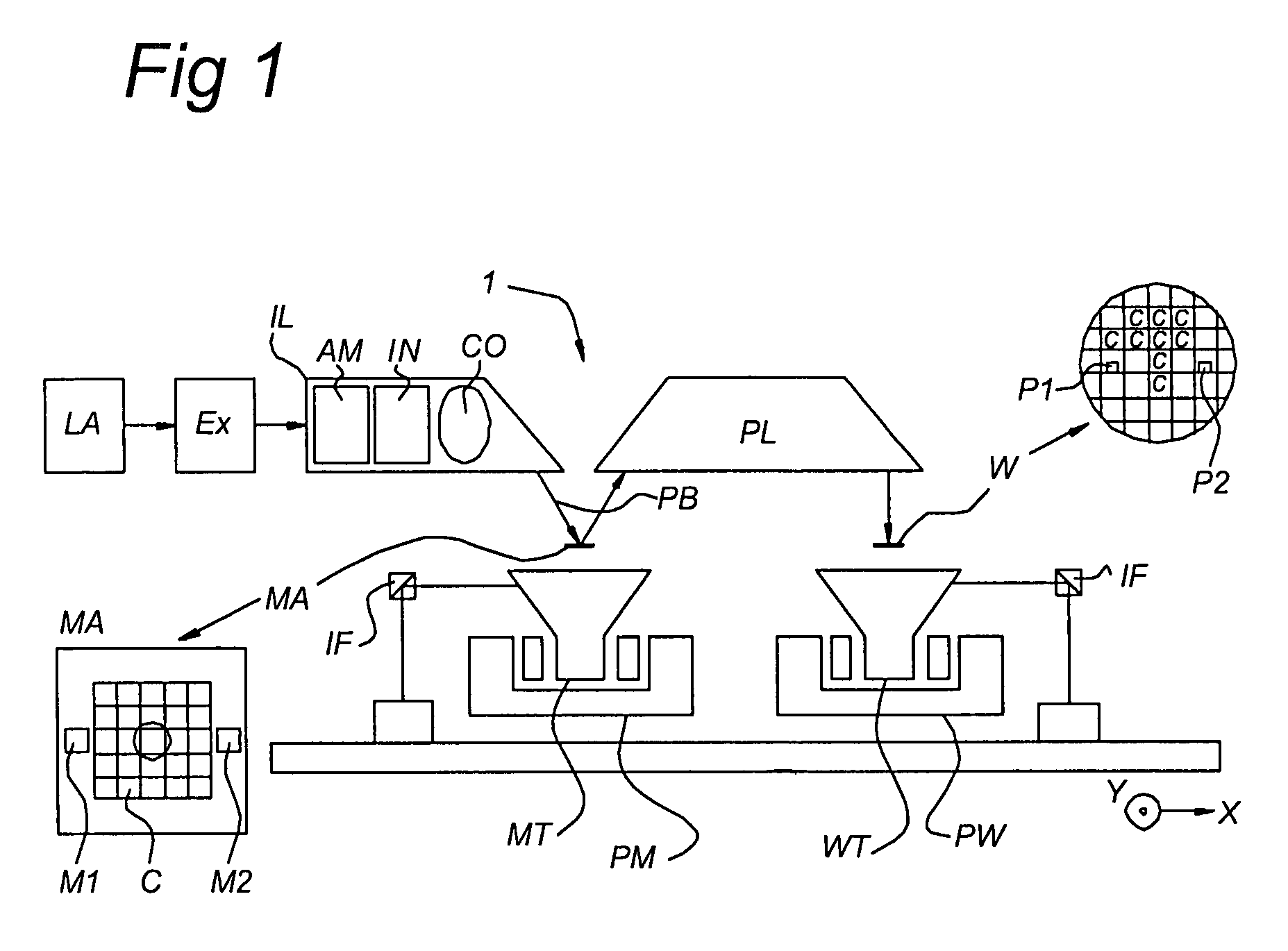
[0037]FIG. 1 schematically depicts a lithographic projection apparatus 1 according to an embodiment of the invention. The apparatus comprises: a radiation system Ex, IL, for supplying a projection beam PB of radiation (e.g. EUV radiation) with a wavelength of 11-14 nm. In this particular case, the radiation system also comprises a radiation source LA; a first object table (mask table) MT provided with a mask holder for holding a patterning device, illustrated in the form of the mask MA (e.g. a reticle), and connected to first positioning structure PM for accurately positioning the mask with respect to item PL; a second object table (substrate table) WT provided with a substrate holder for holding a substrate W (e.g. a resist-coated silicon wafer), and connected to second positioning structure PW for accurately positioning the substrate with respect to item PL; and a projection system (“lens”) PL for imaging an irradiated portion of the mask MA onto a target portion C (e.g. comprisin...


PUM

PropertyMeasurementUnit
wavelengthaaaaaaaaaa

Abstract

An assembly for capacitively detecting an object on a support structure includes at least one electrode being arranged in the vicinity of the support structure, and at least one cable being connected to the at least one electrode. The at least one cable has a first conductor and a second conductor. The first conductor is connected to a series connection of a DC source and a first AC source. A control device is arranged to control the DC source to provide a predetermined DC voltage to the at least one electrode to provide a clamping force on the object, and control the first AC source to provide a predetermined first AC voltage with a first amplitude and a first phase via the first conductor to the at least one electrode for capacitively detecting the object. The assembly includes a second AC source connected to the second conductor and the control device is arranged to control the second AC source to provide a predetermined second AC voltage to the second conductor. The second AC voltage has a second amplitude and a second phase, respectively, which are substantially equal to the first amplitude and first phase, respectively.

Description

[0001]The present application claims priority to European Application No. 03075128.3, filed on Jan. 15, 2003, the entirety of which is hereby incorporated into the present application by reference thereto.BACKGROUND OF THE INVENTION[0002]1. Field of the Invention[0003]The invention relates to detecting an object on a support structure.[0004]2. Brief Description of Related Art[0005]Detection assemblies are particularly advantageously provided in a lithographic projection apparatus. Aspects of the present invention shall therefore hereinafter be illustrated by a lithographic apparatus by way of example only. In a lithographic projection apparatus, the presence of an object on a support structure is currently detected by measuring the capacitance of an assembly comprising at least cables connected to the support structure and the support structure itself. It is impossible to measure the capacitance of the support structure only, because the measurement of the capacitance of the support...

Claims


Application Information

Patent Timeline
Patent Type & Authority Patents(United States)
IPC IPC(8): G01R27/26G03F7/20G03F9/00H01L21/027H01L21/67
CPCG03F7/7085G03F7/707B01D46/76
Inventor TINNEMANS, PATRICIUS ALOYSIUS JACOBUS
Owner ASML NETHERLANDS BV
Why Eureka
Try Eureka