Switchable optical element

a technology of optical elements and switches, applied in the field of switches, can solve the problems of limited lifespan, mechanical moving parts are subject to wear, and can be relatively large and expensive to produce, and achieve the effect of high degree of uniformity

Active Publication Date: 2009-03-24
KONINKLIJKE PHILIPS ELECTRONICS NV
View PDF17 Cites 123 Cited by
  • Summary
  • Abstract
  • Description
  • Claims
  • Application Information

AI Technical Summary

Benefits of technology

[0009]Such a device can be designed with non-circular or other shaped active areas. Also, the second fluid does not need to contact an interior surface of the fluid chamber to provide a substantial change in transmissivity, therefore the problem of separating the second fluid from such a surface does not arise. Furthermore, a substantially planar interface between the first and second fluids is possible, giving a high degree of uniformity across the element. This also avoids the problem of introducing a lens effect due the boundary between the first and second fluids, meaning a wider range of fluids can be used in the switchable element and therefore fewer compromises have to be made in fluid selection. Moreover, a substantially planar interface allows the element to be thin.

Problems solved by technology

However, mechanical moving parts can be relatively large and expensive to produce.
Furthermore, mechanical moving parts are subject to wear, so have a limited lifespan and may suffer from reliability problems during their lifespan.
Firstly, the device 100 is relatively inflexible as the shape of the area of contact is hard to control to be anything other than circular.
Secondly, in practice it may be difficult to separate the second fluid 102 from the interior surface of the container 103 when changing from an on state (FIG. 13) to an off state (FIG. 12).
Thirdly, in the off state the curvature of the interface 104 between the two fluids means that the device may not have uniform transmission characteristics across its area.
Fourthly, due to the curved surface, the optically active area is significantly smaller than the actual size of the device.
Therefore, the range of fluids available for use in the device is relatively restricted, and to achieve a working device compromises may have to be made on some properties.

Method used


Image

  • Switchable optical element
  • Switchable optical element
  • Switchable optical element

Examples


Embodiment Construction

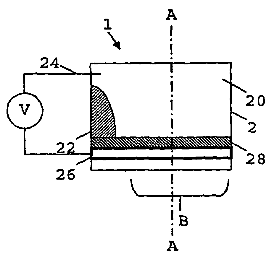
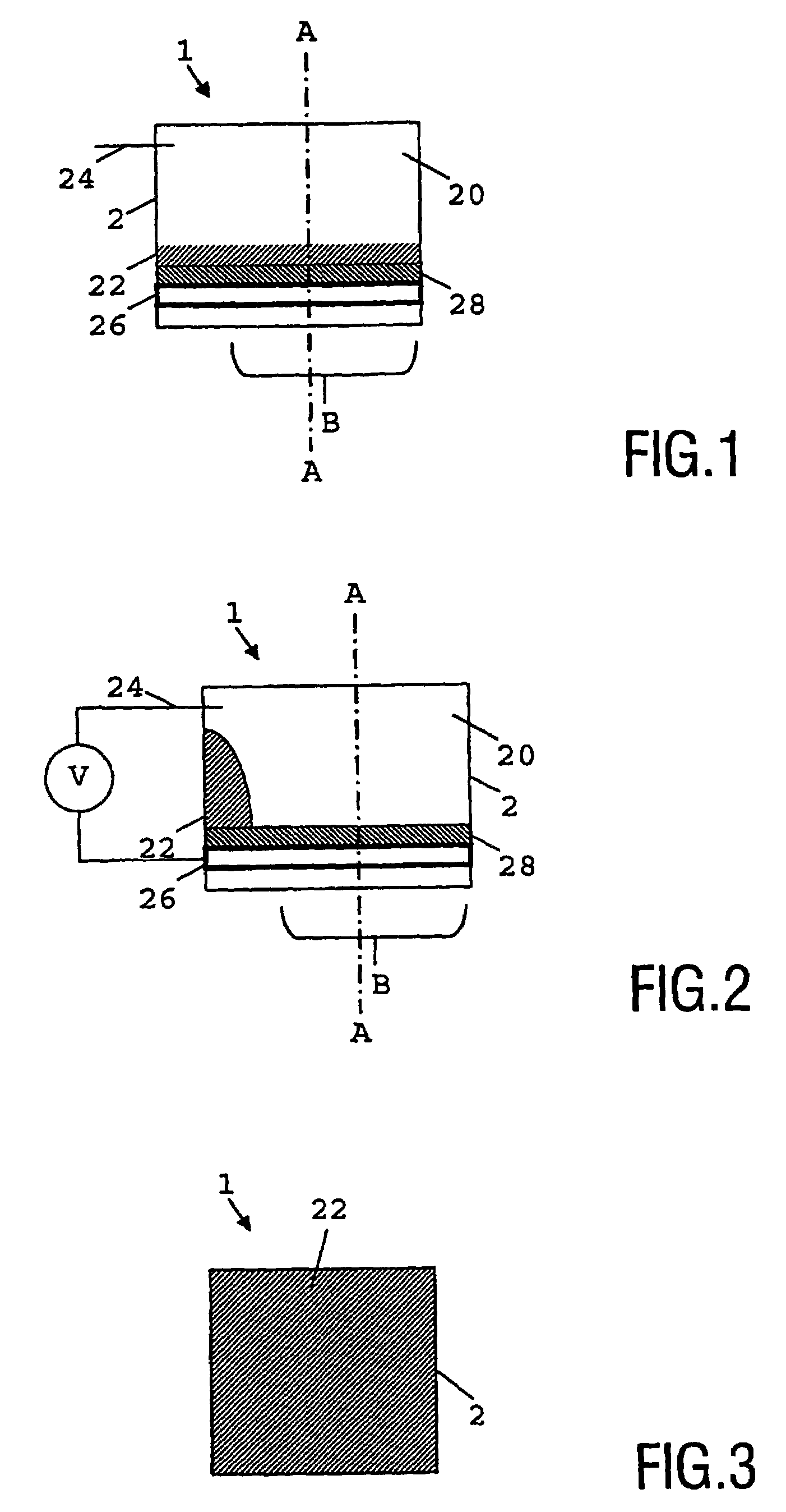
[0028]The present inventors have realised that it is possible to overcome the drawbacks associated with the device 100 of FIGS. 12 and 13, and have provided a switchable optical element which is compact, has no mechanical moving parts and can be used in a number of applications. By providing a switchable optical element in which a body of fluid is arranged to move substantially transverse to the optical axis of the element it is possible to achieve a large number of effects, for example a variable aperture diaphragm, a switchable colour filter and a shutter. The operation of a first embodiment of the present invention working as a shutter will now be described.

[0029]FIG. 1 shows a side view of a switchable optical element 1 according to a first preferred embodiment of the present invention in a first state. The optical axis of the switchable optical element 1 is parallel to the line A-A, and the active area of the device extends over the region B. The switchable optical element 1 co...


PUM

PropertyMeasurementUnit
diametersaaaaaaaaaa
diameteraaaaaaaaaa
wettabilityaaaaaaaaaa

Abstract

A switchable optical element has a fluid chamber including immiscible first and second bodies of fluid disposed relative to one another along an optical axis of the element. The second body of fluid is movable in a direction away from the optical axis (A) by electro-wetting action, giving the switchable optical element a changeable transmissivity along the optical axis.

Description

FIELD OF THE INVENTION[0001]The present invention relates to switchable optical elements, to optical devices including switchable optical elements. The present invention further relates to methods of manufacturing switchable optical elements and to methods of manufacturing optical scanning devices. The switchable optical element is particularly suitable for, but not limited to use as an optical diaphragm, shutter or colour filter.BACKGROUND OF THE INVENTION[0002]Switchable optical elements including shutters, diaphragms etc. based on mechanical moving parts are known. Switchable optical elements based on mechanical moving parts have optical transmission properties that can be switched between predetermined states of differing optical transmittance, for example, states of high or low amplitude attenuation. However, mechanical moving parts can be relatively large and expensive to produce. Furthermore, mechanical moving parts are subject to wear, so have a limited lifespan and may suff...

Claims


Application Information

Patent Timeline
Patent Type & Authority Patents(United States)
IPC IPC(8): G02B26/02G02B3/14G11B7/135
CPCG02B3/14G02B26/005G11B7/1376G11B7/1381G11B7/139G11B7/1398G11B2007/13727G02B26/08G02B26/02G02B26/00
Inventor FEENSTRA, BOKKE JOHANNESHAYES, ROBERT ANDREWSNOEREN, RUDOLPH MARIAKUIPER, STEINHENDRIKS, BERNARDUS HENDRIKUS WILHELMUSVAN ARENDONK, ANTON PETRUS MARIA
Owner KONINKLIJKE PHILIPS ELECTRONICS NV
Why Eureka
Try Eureka