Optical system, finder optical system, relay type finder optical system, eyepiece optical system, and single-lens reflex camera

a technology of optical system and optical axis, which is applied in the field of optical system, finder optical system, finder optical system, relay type finder optical system, eyepiece optical system and single-lens reflex camera, can solve the problems of image shape asymmetric with respect to the optical axis, image-formation capability deterioration, and decentration distortion, etc., and achieve the effect of wide field

Inactive Publication Date: 2009-03-24
OLYMPUS CORP
View PDF9 Cites 4 Cited by
  • Summary
  • Abstract
  • Description
  • Claims
  • Application Information

AI Technical Summary

Benefits of technology

[0028]Another object of the invention is to provide a compact relay type finder optical system that is compatible with a single-lens reflex camera using a relatively small image pickup device, and a single-lens reflex camera incorporating it.
[0029]Yet another object of the invention is to provide an eyepiece optical system that has a relatively wide field of view, a long distance (eye relief) from an eyepiece lens to a viewer's pupil (eye point) and a compact total length including an image viewing position by an image-formation lens.

Problems solved by technology

As this anti-shake group is decentered, it produces aberrations that lead to image-formation capability deteriorations.
It also produces decentration distortion that may otherwise cause an image shape to turn asymmetric with respect to the optical axis.
Further, as the anti-shake group is heavy, it gives an increasing load to an actuator for the movement of the anti-shake group; that is, it is necessary to lighten the anti-shake group.
Furthermore, a low sensitivity to anti-shake causes an increase in the amount of movement of the anti-shake group.
A high sensitivity to anti-shake, in contrast, renders control of movement of the anti-shake group difficult.
In other words, these prior arts are still less than satisfactory in terms of practically optimum anti-shake methods, and how they are feasible.
Although it is necessary to shorten the focal length of the whole finder optical system so as to make finder magnification high, this renders it difficult to set up a finder system in a widely available penta prism mode.
However, although they have a sufficiently wide angle of view, yet they are of inadequate eye relief.

Method used


Image

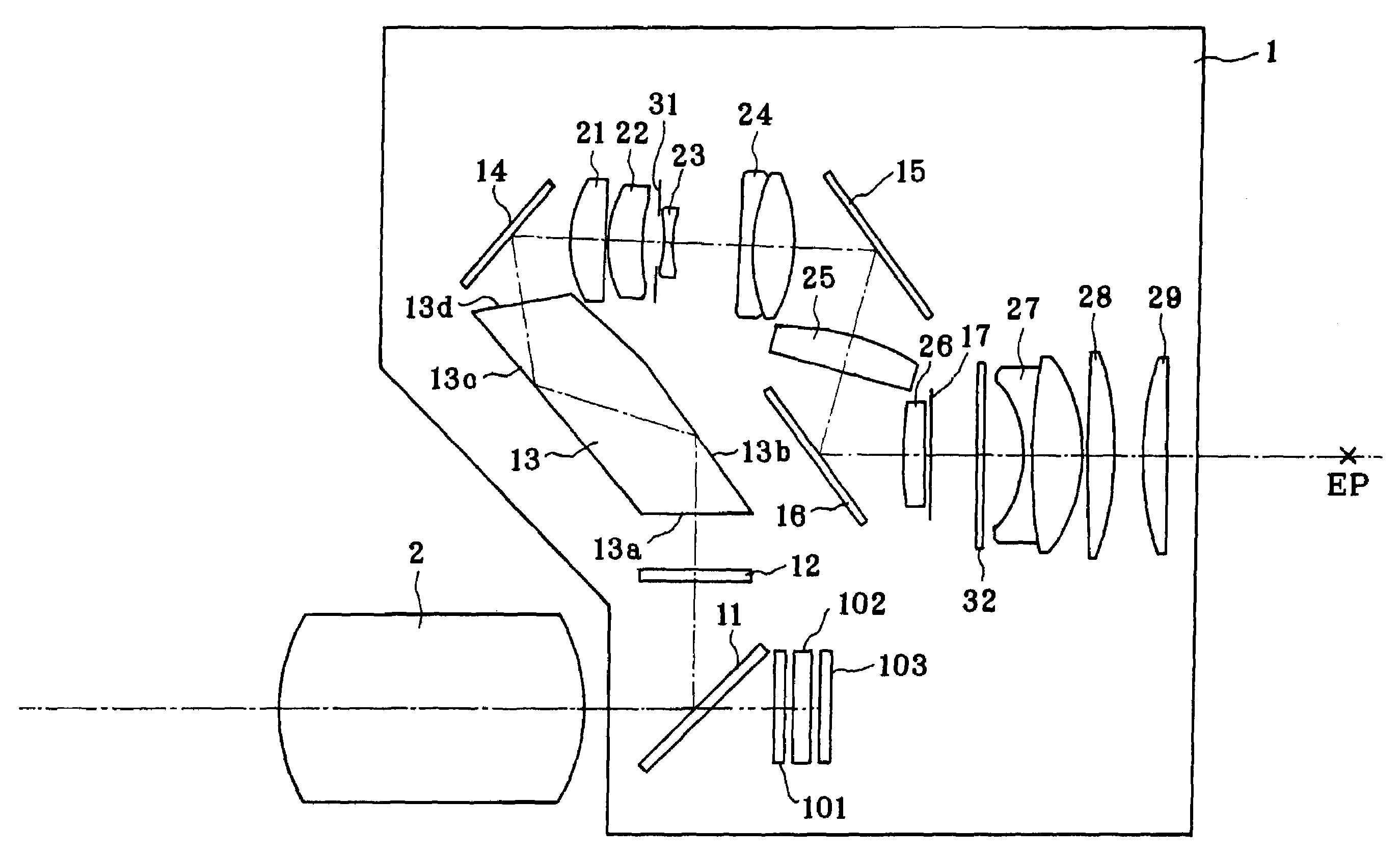
  • Optical system, finder optical system, relay type finder optical system, eyepiece optical system, and single-lens reflex camera
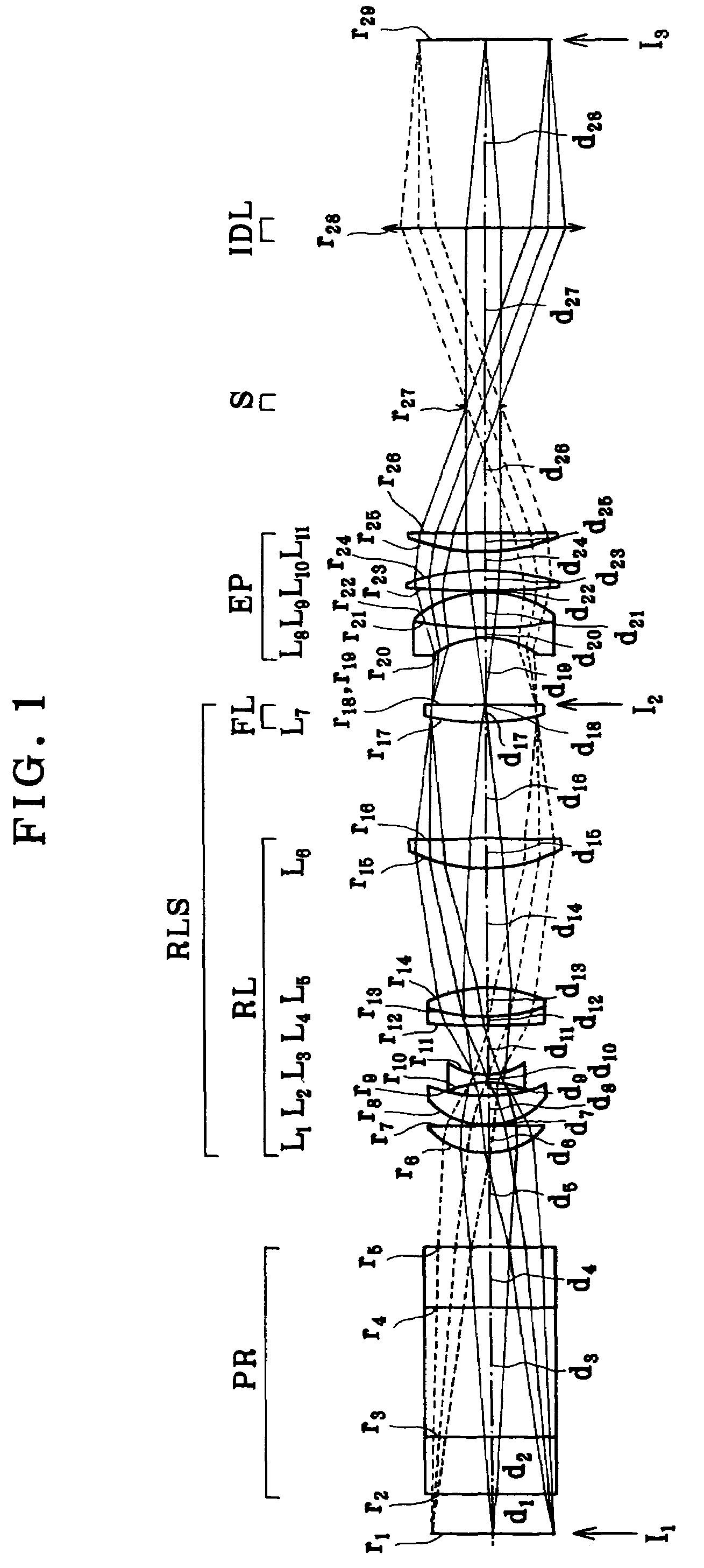
  • Optical system, finder optical system, relay type finder optical system, eyepiece optical system, and single-lens reflex camera
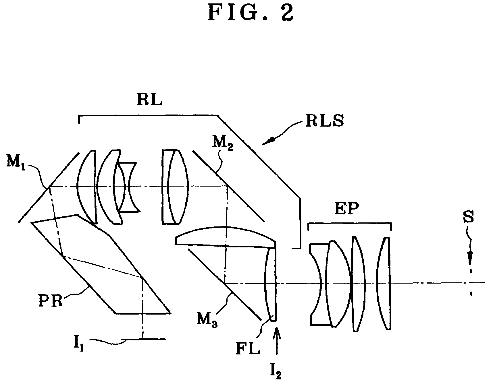
  • Optical system, finder optical system, relay type finder optical system, eyepiece optical system, and single-lens reflex camera

Examples


first embodiment

[0396]the fourth aspect of the invention is directed to an eyepiece optical system characterized by comprising, in order from a side of the image being viewed, a first lens having negative refracting power, a second lens having positive refracting power, a third lens having positive refracting power and a fourth lens having positive refracting power, and satisfying the following condition:

2.5≦f123 / fA≦8   (4-1)

where:

[0397]f123 is the composite focal length of the first lens, the second lens and the third lens, and

[0398]fA is the focal length of the whole eyepiece optical system.

[0399]The advantage of, and the requirement for, the above first embodiment is now explained.

[0400]In this eyepiece optical system comprising the first to the fourth lens, there is a −+ sharing of power in order from the side of the image being viewed, so that the principal points are located on the pupil side. This allows the space between the image being viewed and the eyepiece optical system to become so na...

second embodiment

[0404]the fourth aspect of the invention is directed to an eyepiece optical system characterized by comprising, in order from a side of the image being viewed, a first lens having negative refracting power, a second lens having positive refracting power, a third lens having positive refracting power and a fourth lens having positive refracting power, and satisfying the following condition:

1≦f4 / fA≦2   (4-2)

where:

[0405]f4 is the focal length of the fourth lens, and

[0406]fA is the focal length of the eyepiece optical system.

[0407]The advantage of, and the requirement for, the above second embodiment is now explained.

[0408]In this eyepiece optical system comprising the first to the fourth lens, there is a −+ sharing of power in order from the image being viewed, so that the principal points are located on the pupil side. This allows the space between the image being viewed and the eyepiece optical system to become so narrow that the total length of the eyepiece optical system including ...

third embodiment

[0412]the fourth aspect of the invention is directed to an eyepiece optical system characterized by comprising, in order from the image being viewed, a first lens having negative refracting power, a second lens having positive refracting power, a third lens having positive refracting power and a fourth lens having positive refracting power, and satisfying the following condition:

0.02≦d4 / fA≦0.2   (4-3)

where:

[0413]d4 is the axial thickness of the fourth lens, and

[0414]fA is the focal length of the eyepiece optical system.

[0415]The advantage of, and the requirement for, the above third embodiment is now explained.

[0416]In this eyepiece optical system comprising the first to the fourth lens, there is a −+ sharing of power in order from the image being viewed, so that the principal points are located on the pupil side. This allows the space between the image being viewed and the eyepiece optical system to become so narrow that the total length of the eyepiece optical system including the...


PUM


Abstract

The invention concerns an optical system adapted to split an optical path from a taking optical system into a finder optical system, which has a camera-shake correction function best suited for the finder optical system, and so on. This optical system comprises a taking optical system and a finder optical system. The taking optical system comprises an optical path splitter means operable to split an optical path into the finder optical system, and the finder optical system includes a relay optical system RLS for re-forming a subject image once. Anti-shake is implemented by shifting an optical subsystem RL that forms a part of the finder optical system in a plane vertical to an optical axis.

Description

[0001]This application claims benefits of Japanese Application No. 2005-3395 filed in Japan on Jan. 11, 2005 and Japanese Application Nos. 2005-79097, 2005-79098, 2005-79099 and 2005-79100 filed in Japan on Mar. 18, 2005, the contents of which are incorporated by this reference.BACKGROUND OF THE INVENTION[0002]The present invention relates generally to an optical system, a finder optical system, a relay type finder optical system, an eyepiece optical system and a single-lens reflex camera, and more specifically to an optical system having a camera-shake correction function capable of preventing image-shakes by camera-shake (e.g., upon hand-hold photographing), a relay optical system designed especially for taking systems such as digital cameras, film cameras and video cameras, an eyepiece optical system having a wide field of view, a long eye relief and a compact total length, a compact relay type finder optical system using the same, and a single-lens reflex camera using the same.[...

Claims


Application Information

Patent Timeline
Patent Type & Authority Patents(United States)
IPC IPC(8): G03B13/08
CPCG03B5/04G02B13/22G03B19/12
Inventor TOCHIGI, AKIYOSHIMITSUO, TERUHISAKUBA, KEIICHIGOTO, HISASHI
Owner OLYMPUS CORP
Why Eureka
Try Eureka