Heat sink

a heat sink and heat sink technology, applied in the field of heat sinks, can solve the problems of difficult to efficiently remove heat from electronic packages in the heat sinks

Inactive Publication Date: 2009-03-31
HONG FU JIN PRECISION IND (SHENZHEN) CO LTD +1
View PDF13 Cites 5 Cited by
  • Summary
  • Abstract
  • Description
  • Claims
  • Application Information

AI Technical Summary

Benefits of technology

[0003]Generally, a heat sink comprises a base contacting the electronic package for absorbing heat from the electronic package, and a plurality of fins extending perpendicularly from the base to dissipate the heat deriving from the electronic package. A fan is mounted onto the heat sink to facilitate air convection in the heat sink to enhance the heat dissipation efficiency of the heat sink. However, airflow resistance makes most of current heat sinks difficult to efficiently remove heat from the electronic packages which generate a great deal of heat during operation.

Problems solved by technology

However, airflow resistance makes most of current heat sinks difficult to efficiently remove heat from the electronic packages which generate a great deal of heat during operation.

Method used


Image

  • Heat sink
  • Heat sink
  • Heat sink

Examples


Embodiment Construction

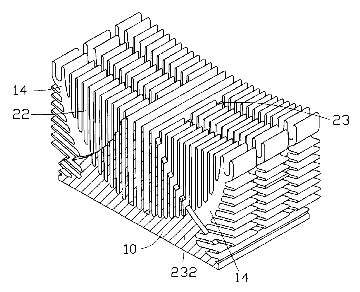
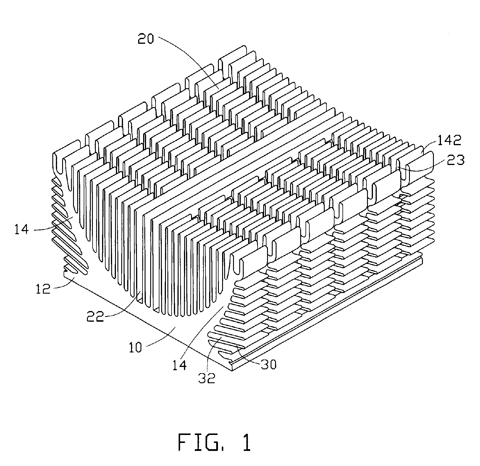
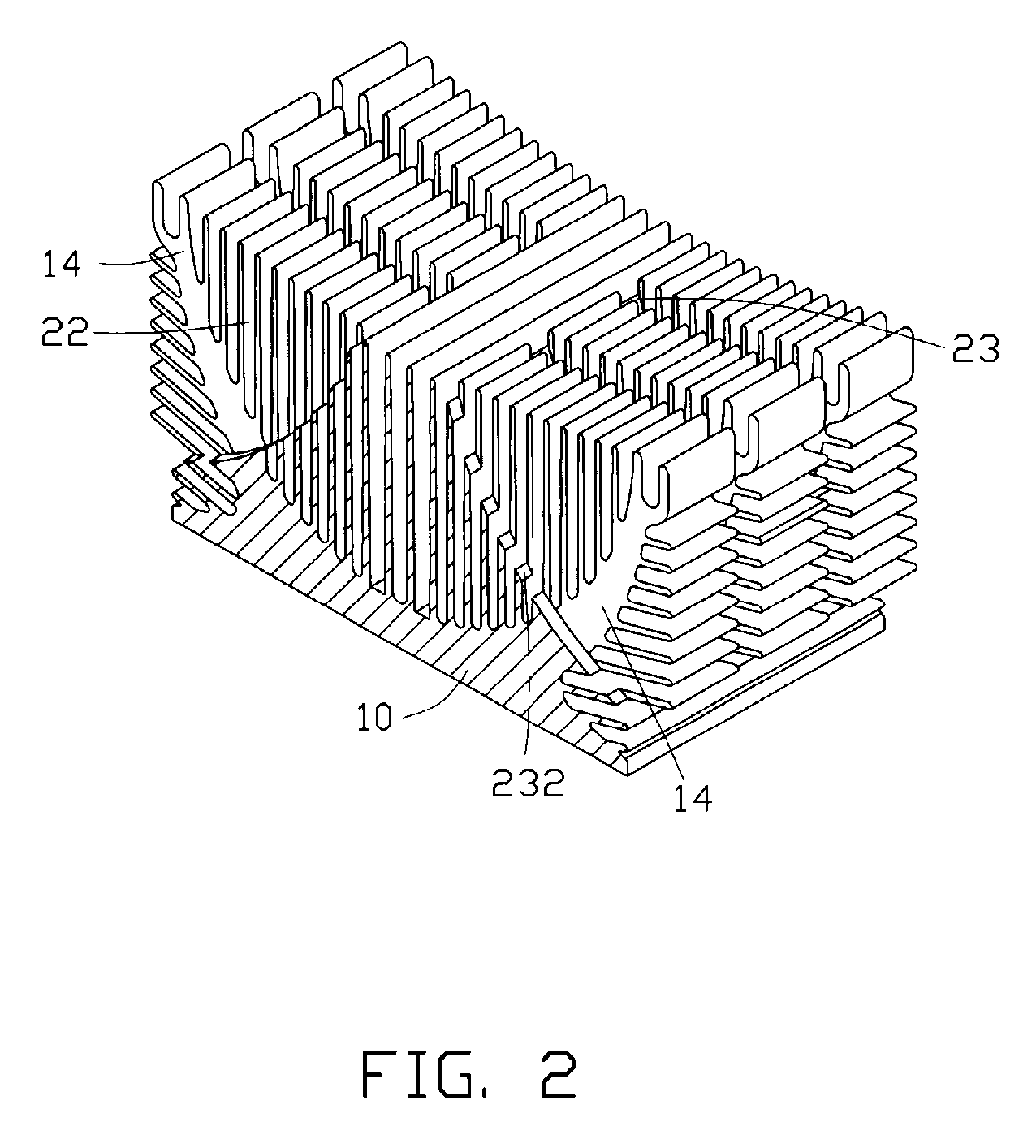
[0011]Referring to FIGS. 1-3, a heat sink in accordance with a preferred embodiment of the present invention is illustrated. The heat sink is used to remove heat from a heat source (not shown), such as a Central Processing Unit, a chip set, etc.

[0012]The heat sink is made of a heat conductive material, such as copper, aluminum, etc. In the preferred embodiment, the heat sink is formed first by aluminum alloy extrusion and then machining. The heat sink comprises a solid base 10 adapted for contacting a surface of the heat source, a plurality of vertical fins 20 and a plurality of lateral fins 30. The base 10 is used to absorb heat generated by the heat source. The fins 20, 30 are used to dissipate the heat to ambient air.

[0013]The base 10 comprises a flat substrate 12 having a flat bottom surface to contact the heat source and a pair of wings 14. The wings 14 are respectively extend upwardly and outwardly from a center of the substrate 12 to render the wings 14 to have a substantiall...


PUM


Abstract

A heat sink includes a first array of fins defining a plurality of first channels therebetween, a second array of fins disposed at opposite sides of the first array of fins, and a plurality of grooves extending through the first array of fins and the second array of fins. The second array of fins defines a plurality of second channels therebetween. The grooves are intersected with the first channels and the second channels. A bottom extremity of each groove has a curved shape facing upwardly and laterally. A portion of an airflow generated by a fan mounted on a top of the heat sink flows laterally and downwardly through the grooves to leave the heat sink.

Description

FIELD OF THE INVENTION[0001]The present invention relates to a heat sink, and more particularly to a heat sink for removing heat from an electronic package and dissipating the heat to ambient air.DESCRIPTION OF RELATED ART[0002]A heat sink is usually placed in thermal contact with an electronic package, such as a central processing unit (CPU), to transfer heat through conduction away from the electronic package, thus preventing over-heating of the electronic package.[0003]Generally, a heat sink comprises a base contacting the electronic package for absorbing heat from the electronic package, and a plurality of fins extending perpendicularly from the base to dissipate the heat deriving from the electronic package. A fan is mounted onto the heat sink to facilitate air convection in the heat sink to enhance the heat dissipation efficiency of the heat sink. However, airflow resistance makes most of current heat sinks difficult to efficiently remove heat from the electronic packages whic...

Claims


Application Information

Patent Timeline
Patent Type & Authority Patents(United States)
IPC IPC(8): F28F7/00H05K7/20
CPCH01L23/367H01L23/467H01L2924/0002H01L2924/00H01L23/3677
Inventor LIN, YU-CHENXU, HONG-BO
Owner HONG FU JIN PRECISION IND (SHENZHEN) CO LTD
Why Eureka
Try Eureka