Electrical connection box

a technology of electrical connection and connection terminal, which is applied in the direction of electric apparatus casings/cabinets/drawers, gaseous cathodes, transportation and packaging, etc., can solve the problems of large amount of resin material, high cost, and easy physical load on connection terminals, so as to reduce the amount of resin and reduce the amount of heat efficiently. , excellent strength

Inactive Publication Date: 2015-02-17
SUMITOMO WIRING SYST LTD
View PDF12 Cites 4 Cited by
  • Summary
  • Abstract
  • Description
  • Claims
  • Application Information

AI Technical Summary

Benefits of technology

[0006]Exemplary embodiments are devised in view of the foregoing and have an object to provide an electrical connection box of a novel structure provided with an insulating plate not only ensuring strength with a smaller amount of resin but also being capable of enhancing heat dissipation.
[0008]By forming the insulating plate in a penetrating configuration in the honeycomb structure portion, an amount of resin used to form the insulating plate can be reduced. Moreover, despite a reduction in amount of resin, strength can be ensured by adopting the honeycomb structure. It thus becomes possible to reduce the manufacturing costs and a weight of the electrical connection box. Further, because the insulating plate is formed in a penetrating configuration in the honeycomb structure portion, air convection within the electrical connection box is promoted. Heat can be therefore efficiently released from the printed-circuit board on which the insulating plate is superimposed. In other words, the insulating plate itself can have a honeycomb structure in contrast to the related art in which the insulating plate can be provided with a stiffening rib or a configuration thereof. Hence, not only does it become possible to form an insulating plate using a small amount of resin while ensuring strength, but it also becomes possible to enhance heat dissipation.
[0011]By providing the insulating plate with the thin portion having a small plate thickness dimension, it becomes possible, for example, to form an electrical part attachment portion, such as a connector attachment portion, provided to the case of the electrical connection box in closer proximity to the insulating plate by a distance corresponding to a thickness dimension that is reduced by providing the thin portion. Hence, when arranged in this manner, the electrical part attachment portion protrudes less toward the outside of the case than otherwise, which can in turn make the electrical connection box more compact. By forming the thick portion having a large plate thickness dimension in a penetrating configuration by providing the honeycomb structure portion, it becomes possible to form the thick portion with a small amount of resin while ensuring strength.
[0013]By supporting the printed-circuit board on the insulating plate, the connection terminal provided to the printed-circuit board can be supported, too. It thus becomes possible to reduce the possibility of solder cracking or damage to printed wiring by suppressing deformation of the printed-circuit board. Also, because the insulating plate is formed in a penetrating configuration in the honeycomb structure portion, even when the printed-circuit board is superimposed thereon, heat can efficiently be released from the printed-circuit board.
[0015]When configured in this manner, two printed-circuit boards can be supported on the single insulating plate. Also, because the honeycomb structure portion is situated between the two printed-circuit boards, the insulating plate is capable of supporting the two printed-circuit boards with excellent strength. Further, because the insulating plate situated between the both printed-circuit boards is formed in a penetrating configuration, heat can efficiently be released from each of the printed-circuit boards.
[0016]According to a fifth exemplary embodiment, the insulating plate supporting an input load applied on the connection terminal can be provided with the honeycomb structure portion that penetrates through the insulating plate in the plate thickness direction. The honeycomb structure portion can, for example, comprise a plurality of aligned regular hexagonal through-holes penetrating through the thick portion in the plate thickness direction. It thus becomes possible to form the insulating plate by reducing an amount of resin while ensuring strength. Further, because the insulating plate is formed in a penetrating configuration in the honeycomb structure portion, air convection within the electrical connection box is promoted, which can in turn enhance a heat dissipation effect.

Problems solved by technology

In general, the connection terminals are susceptible to a physical load, such as a press force and a pull-out force, at the time of attachment and detachment of electrical parts.
Accordingly, the connection terminals may undergo deformation or the printed-circuit board may undergo deflection, thereby giving rise to solder cracking or damage to printed wiring.
The insulating plate of this structure, however, can require a large amount of a resin material to form the rib.
Using such an insulating plate can therefore raise a problem that not only increases the manufacturing costs but also a weight of the electrical connection box.
Also, because the insulating plate is superimposed on the printed-circuit board entirely, heat dissipation may become poor due to deterioration of air convection.

Method used


Image

  • Electrical connection box
  • Electrical connection box
  • Electrical connection box

Examples


Embodiment Construction

[0028]Hereinafter, exemplary embodiments will be described with reference to the drawings.

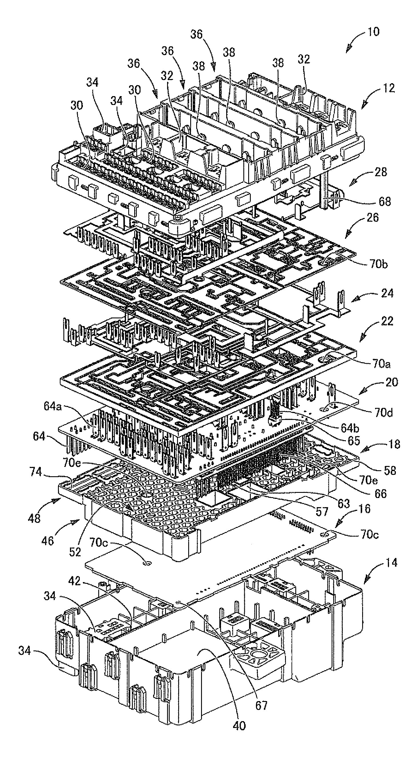
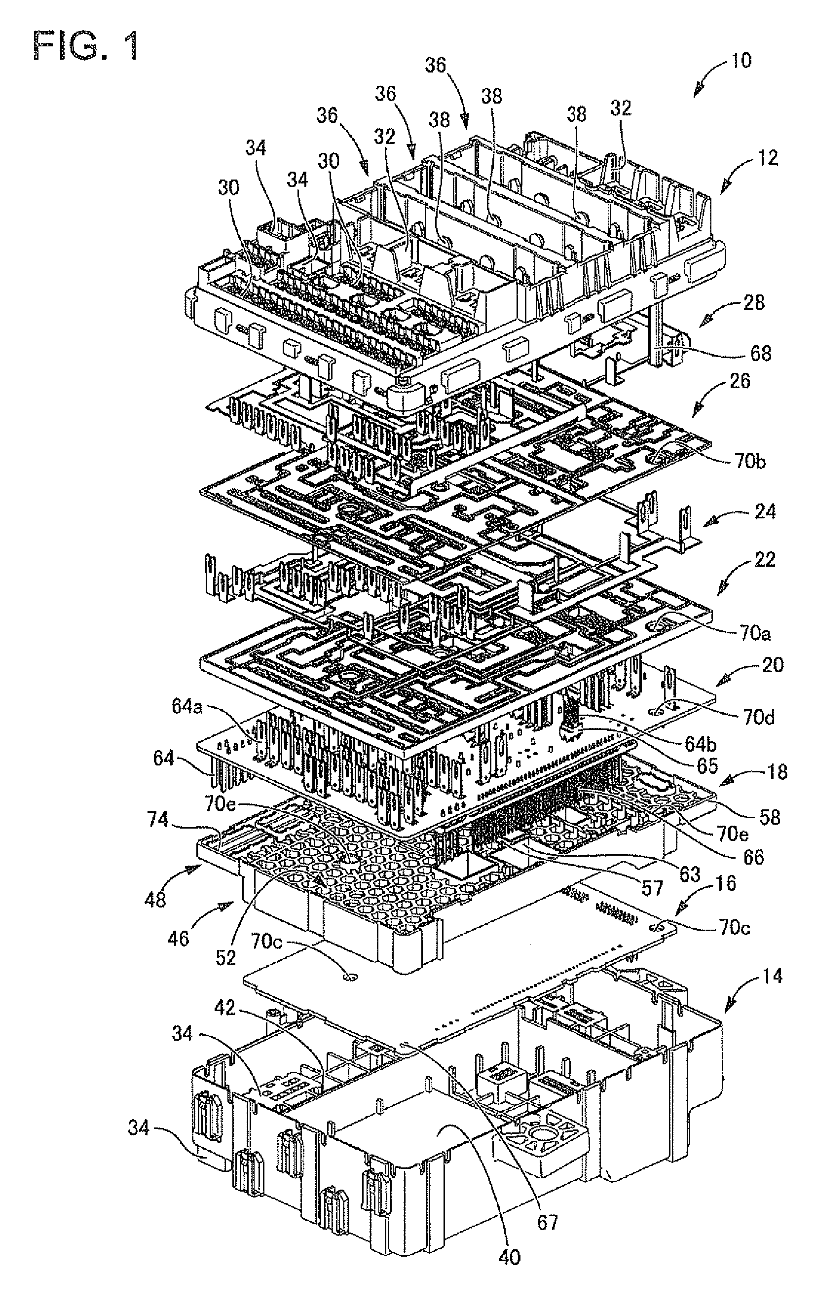
[0029]Firstly, FIG. 1 shows an electrical connection box 10 according to an exemplary embodiment. The electrical connection box 10 is of a structure containing, between an upper case 12 and a lower case 14, a first printed-circuit board 16, an insulating plate 18, a second printed-circuit board 20, a first bus bar insulating plate 22, a first bus bar 24, a second bus bar insulating plate 26, and a second bus bar 28 sequentially laminated in this order from the side of the lower case 14.

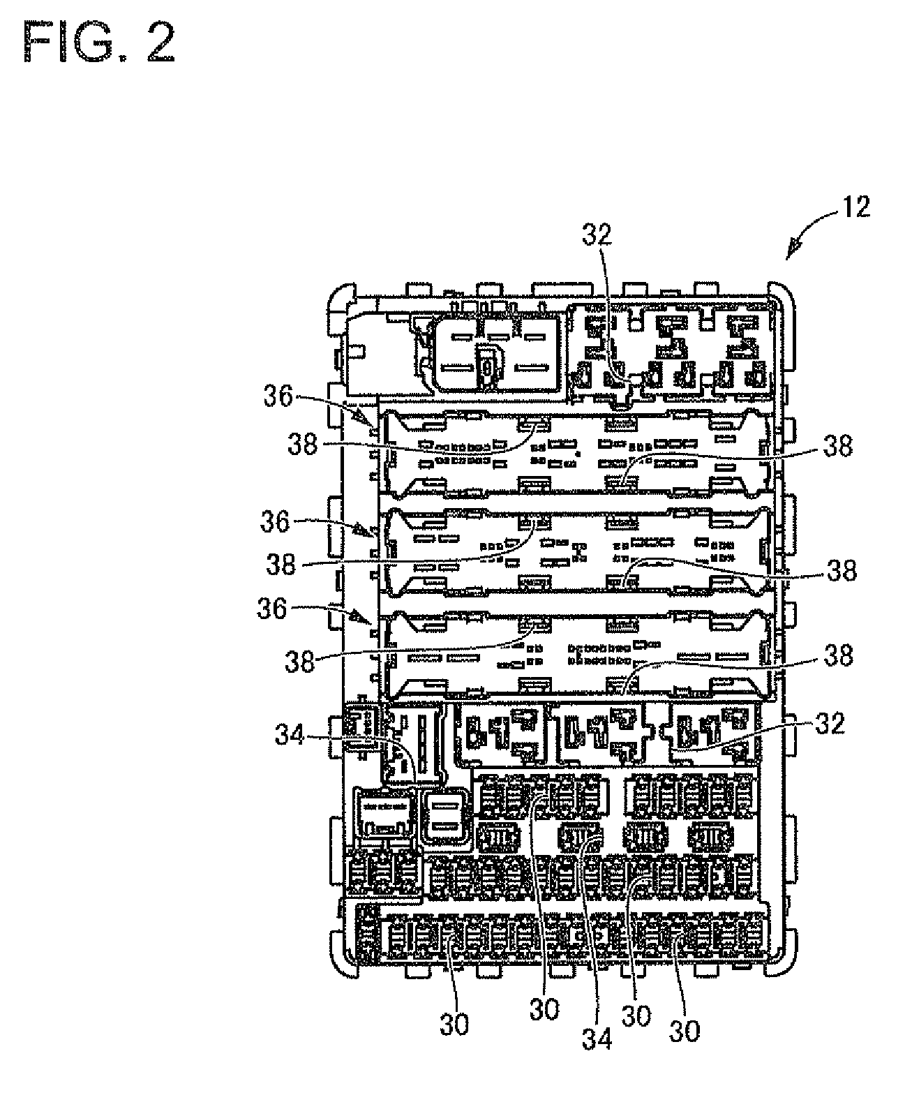
[0030]FIG. 2 shows upper case 12. As electrical part attachment portions, as many known fuse attachment portions 30, relay attachment portions 32, and connector attachment portions 34 as required are provided to the case 12 at appropriate positions. In particular, the upper case 12 of this embodiment is provided with three lever connector attachment portions 36 in parallel. To these lever connector attachment por...


PUM


Abstract

An electrical connection box includes an insulating plate made of resin that supports an input load applied on a connection terminal to be connected to an electrical part. The insulating plate is contained between upper and lower cases and provided with a honeycomb structure portion penetrating through the insulating plate in a plate thickness direction. It thus becomes possible to provide an electrical connection box of a novel structure provided with an insulating plate not only ensuring strength with a smaller amount of resin but also capable of enhancing heat dissipation.

Description

CROSS REFERENCE TO RELATED APPLICATIONS[0001]This application claims priority to JP 2011-024891, filed in Japan on Feb. 8, 2011, the entire disclosure of which is hereby incorporated by reference in its entirety.BACKGROUND[0002]Exemplary embodiments of the present invention relate to an electrical connection box incorporated into an automobile or the like, and more particularly, to an electrical connection box provided with an insulating plate supporting a load applied on a connection terminal.[0003]An electrical connection box, such as a junction box, has been employed in an automobile or the like to efficiently distribute a power supply from a battery to respective electrical components. As is described, for example, in JP-A-2009-26464, such an electrical connection box has an internal circuit formed of a printed-circuit board and a bus bar and the printed-circuit board and the bus bar are provided with connection terminals protruding to the outside of a case and thereby making th...

Claims


Application Information

Patent Timeline
Patent Type & Authority Patents(United States)
IPC IPC(8): H01J5/00H01J15/00H05K5/00H02G3/08B60R16/023
CPCB60R16/0238
Inventor UCHIDA, KUNIHIROSHIMADA, YOSHIHISA
Owner SUMITOMO WIRING SYST LTD
Why Eureka
Try Eureka