Lamp

a technology for lamps and light sources, applied in the field of lamps, can solve the problems of reducing the service life of lamps, and reducing the so as to improve the air convection efficiency of lamps in operation and improve the heat dissipation performan

Active Publication Date: 2010-05-13
ADVANCED CONNECTEK INC
View PDF16 Cites 5 Cited by
  • Summary
  • Abstract
  • Description
  • Claims
  • Application Information

AI Technical Summary

Benefits of technology

[0021]In view of the above, the lamp of the present invention has a plurality of holes for the air to flow in and out, and thus the air convection efficiency of the lamp in operation is improved. Therefore, the lamp of the present invention achieves a better heat dissipation performance.

Problems solved by technology

In particular, the LED applies a current to the compound semiconductor, and releases the excessive energy in the form of light through a combination of electrons and holes.
Generally, high-power LEDs all have problems of heat dissipation.
If the LED operates under an excessively high temperature, the luminous intensity thereof may be attenuated, and the service life thereof may also be shortened.
Therefore, the heat dissipation design of an LED lamp has already become an importation issue focused by researchers in this field.

Method used


Image

  • Lamp
  • Lamp
  • Lamp

Examples


Embodiment Construction

[0026]Reference will now be made in detail to the present embodiments of the invention, examples of which are illustrated in the accompanying drawings. Wherever possible, the same reference numbers are used in the drawings and the description to refer to the same or like parts.

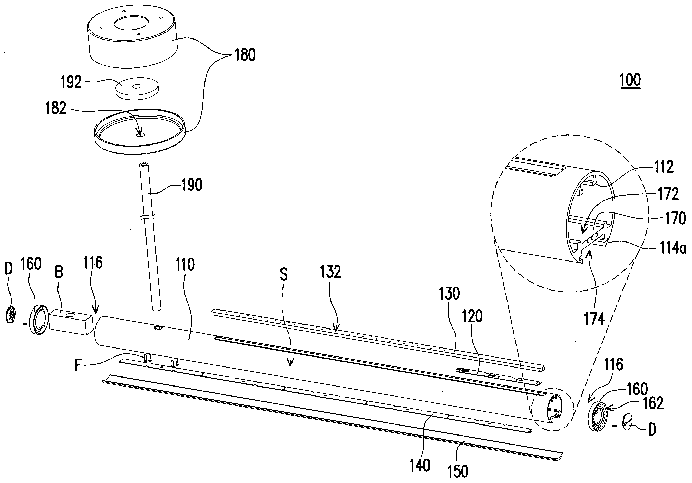
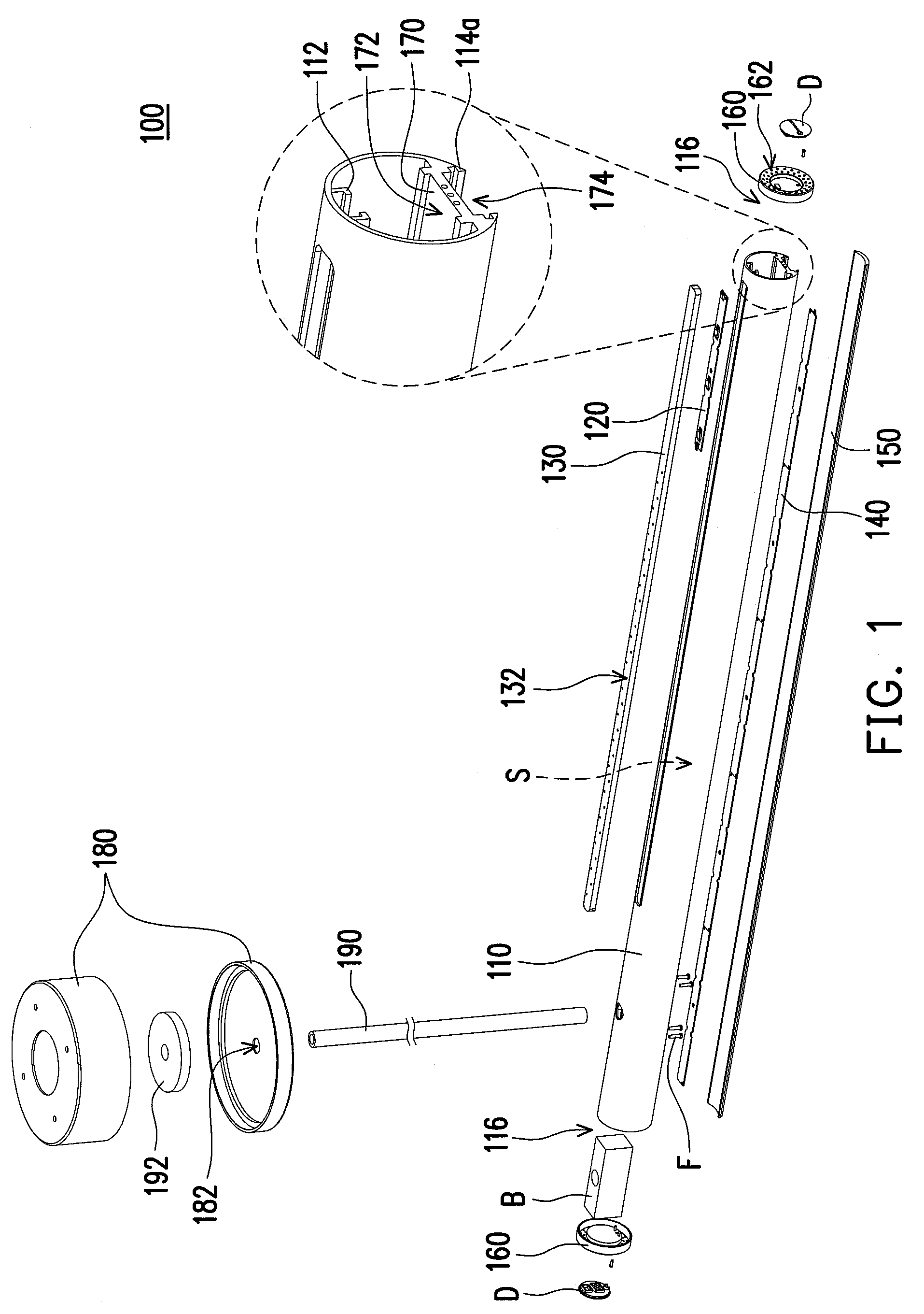
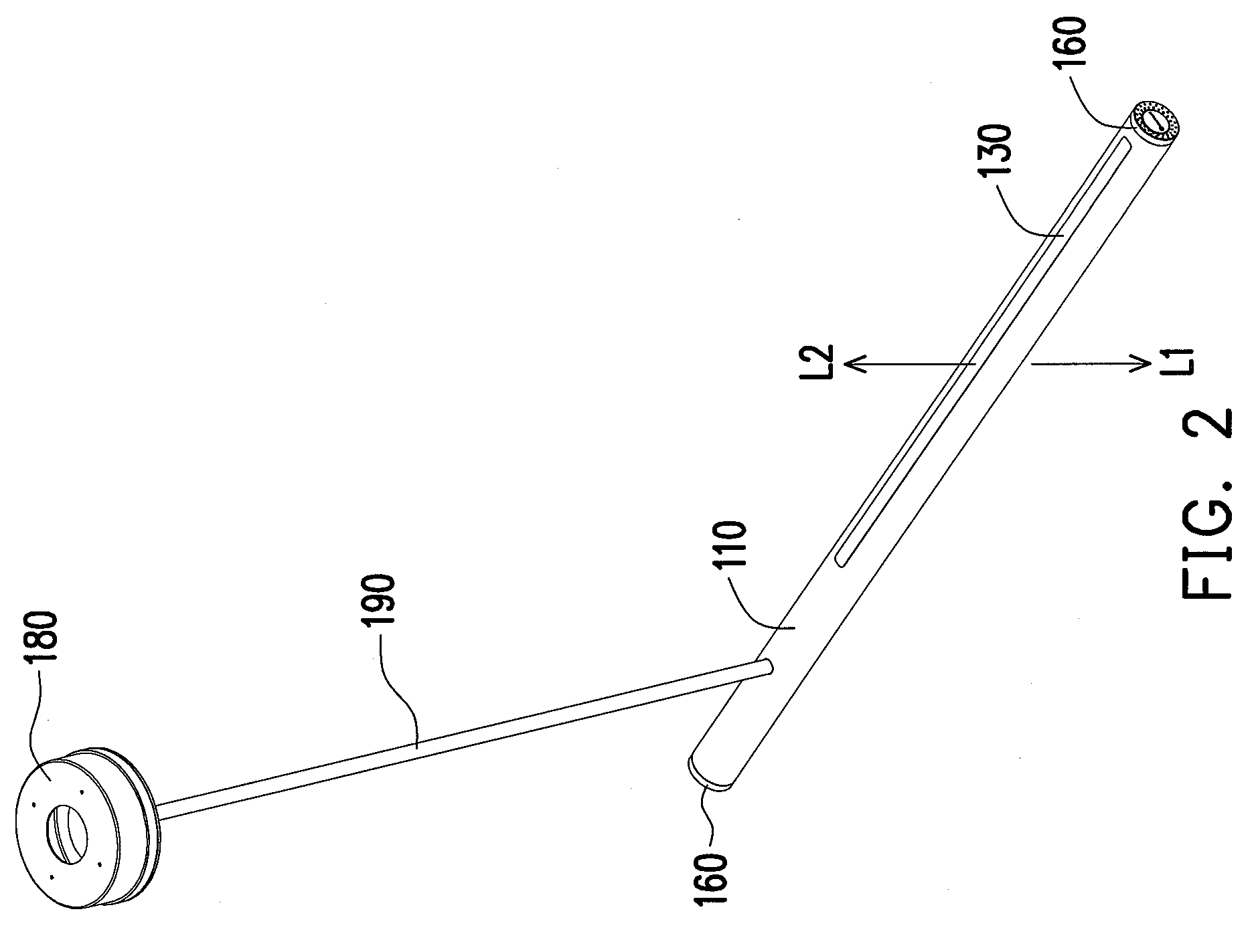
[0027]FIG. 1 is a perspective exploded view of a lamp according to an embodiment of the present invention. FIG. 2 is a perspective view of the lamp in FIG. 1. Referring to FIGS. 1 and 2, a lamp 100 of this embodiment includes a tube-shaped lamp shade 110 with a space S, a first LED light source 120, a first diffuser 130, a second LED light source 140, a second diffuser 150, and two covers 160. A spacer 170 extending along a direction of a length of the tube-shaped lamp shade 110 is disposed in the space S.

[0028]The spacer 170 has a first surface 172 and a second surface 174, and the tube-shaped lamp shade 110 has a first slot 112 and a second slot 114. The first LED light source 120 is disposed on the first su...


PUM


Abstract

A lamp includes a tube-shaped lamp shade with a space, a first light-emitting diode (LED) light source, a first diffuser, a second LED light source, a second diffuser, and two covers. A spacer extending along the direction of the length of the tube-shaped lamp shade is disposed in the space. The spacer has a first surface and a second surface, and the tube-shaped lamp shade has a first slot and a second slot. The first LED light source is disposed on the first surface. The first diffuser is disposed in the first slot, and a first hole is formed at the first diffuser. The second LED light source is disposed on the second surface. The second diffuser is disposed in the second slot. The two covers are disposed at two ends of the tube-shaped lamp shade respectively, and each cover has a second hole.

Description

CROSS-REFERENCE TO RELATED APPLICATION[0001]This application claims the priority benefit of Taiwan application serial no. 97220147, filed on Nov. 10, 2008. The entirety of the above-mentioned patent application is hereby incorporated by reference herein and made a part of this specification.BACKGROUND OF THE INVENTION[0002]1. Field of the Invention[0003]The present invention generally relates to a lamp, in particular, to a lamp which utilizes LEDs as its light source.[0004]2. Description of Related Art[0005]Light-emitting diodes (LEDs) are semiconductor devices. A light-emitting chip of the LED is mainly made of a compound of Group III-V Elements, for example, GaP or GaAs. The light-emitting principle of the LED is to convert electric energy into light energy. In particular, the LED applies a current to the compound semiconductor, and releases the excessive energy in the form of light through a combination of electrons and holes. As the light emission phenomenon of the LED is not ac...

Claims


Application Information

Patent Timeline
Patent Type & Authority Applications(United States)
IPC IPC(8): F21V1/00F21K7/00
CPCF21S8/031F21V9/08F21V29/004F21Y2101/02F21Y2103/003F21V29/83F21S4/008F21V1/04F21V15/013F21Y2103/00F21V29/74F21K9/17F21S4/28F21K9/27F21Y2103/10F21Y2115/10F21Y2107/90
Inventor CHIEN, WEN-HSIANG
Owner ADVANCED CONNECTEK INC
Why Eureka
Try Eureka