Wing assembly and aircraft

a technology for aircraft and wing assemblies, applied in the field of aircraft, can solve problems such as providing pilots with extremely difficult flying challenges

Active Publication Date: 2009-03-31
BERTELSEN DEISGN
View PDF4 Cites 16 Cited by
  • Summary
  • Abstract
  • Description
  • Claims
  • Application Information

AI Technical Summary

Benefits of technology

[0005]In one implementation, the first and second actuators are coupled to the wing through respective first and second carriages that permit generally linear movement of the moveable portion of the wing assembly and the wing. The wing assembly is also permitted to pivot so that the wing may readily reach a position wherein the forces acting on the wing are balanced to provide pitch control, pitch trim and pitch stability in a wide range of flight modes and preferably even during rapid transitions between flight modes. In another implementation, the wing is carried by a wing spar that is moveable relative to the body of the aircraft. The wings are moveable relative to the wing spar, and the wing spar is carried by the body for pivoted movement to provide the desired adjustment and movement of the wing assembly and wing in operation of the aircraft. In yet another implementation, the wing spar is carried by the body for pivoted movement and the wing is carried for pivoted and translational movement relative to the wing spar. This permits the desired adjustment and movement of the wing assembly and wing in operation of the aircraft.

Problems solved by technology

Aircraft of this type have been met with varied success due to the challenges in transitioning between vertical flight and normal horizontal flight.
When transitioning between the vertical and horizontal flight, pitch control, pitch trim and pitch stability are difficult to regulate, thereby providing a pilot with extremely difficult flying challenges.

Method used


Image

  • Wing assembly and aircraft
  • Wing assembly and aircraft
  • Wing assembly and aircraft

Examples


Embodiment Construction

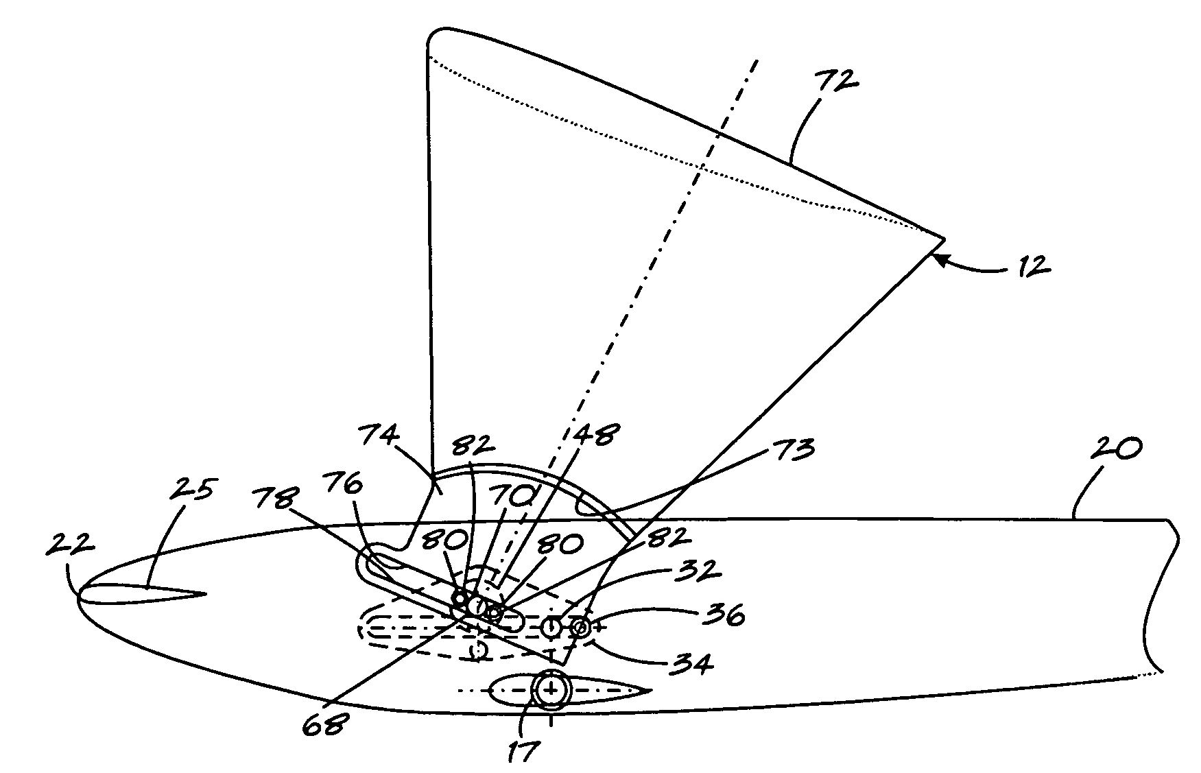
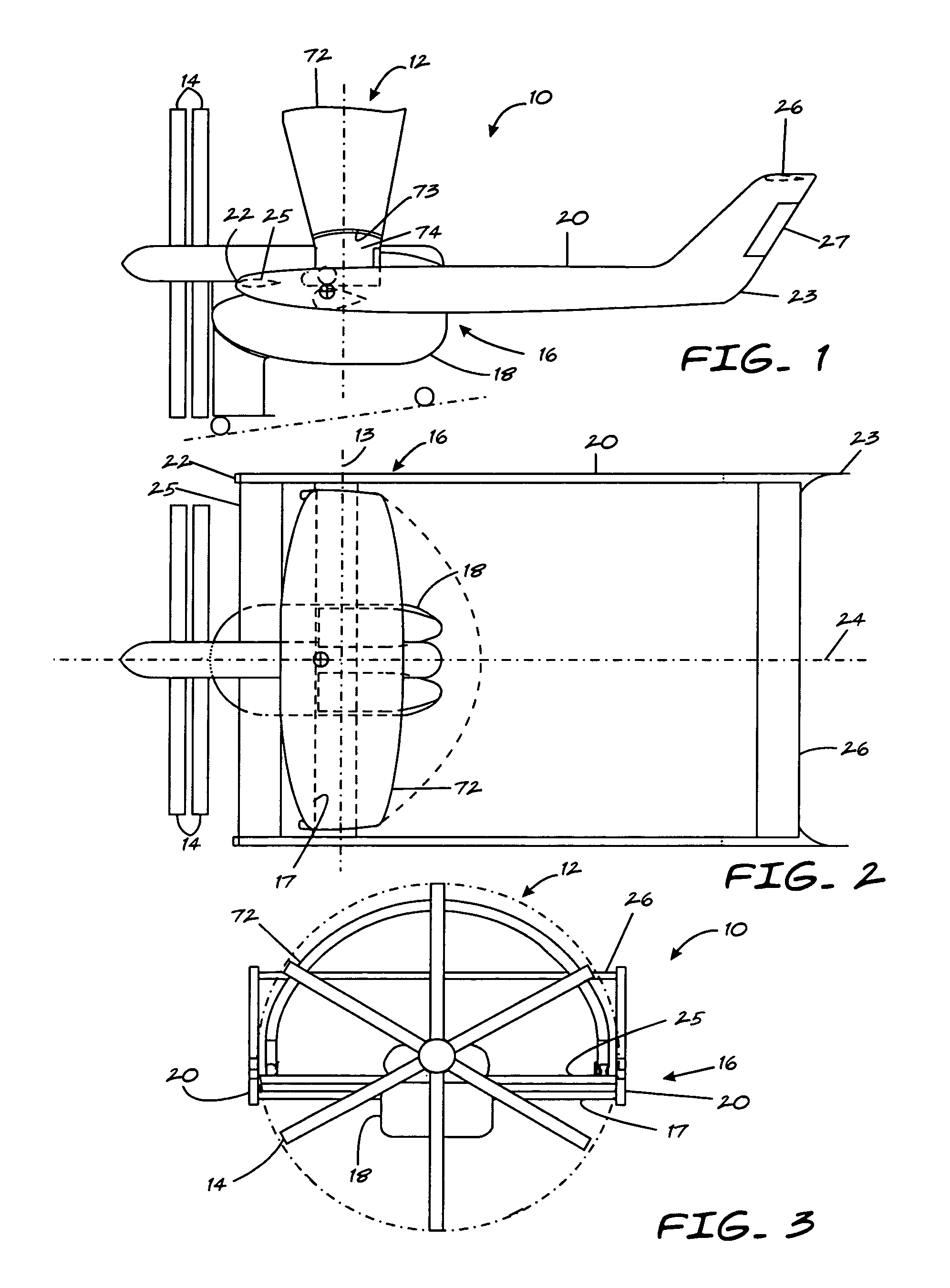
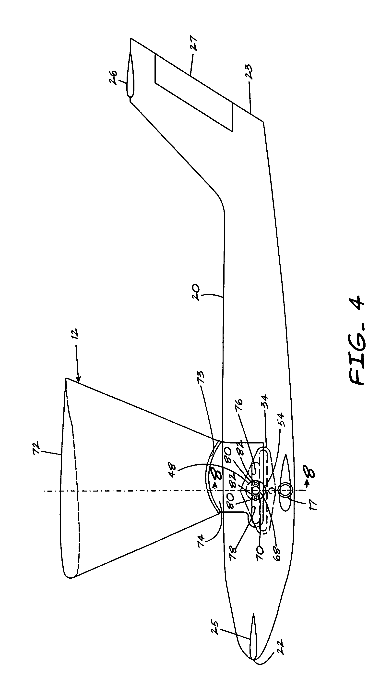
[0028]Referring in more detail to the drawings, FIGS. 1-3 illustrate an aircraft 10 having one presently preferred embodiment of a wing assembly 12. The wing assembly 12 is disposed in a slipstream of a source of propulsion, represented here, by way of example and without limitations, as a propeller or pair of counter-rotating propellers 14 carried by a body or fuselage 16. The wing assembly 12 could include a flap or flaps (not shown) to facilitate re-direction or deflection of the propeller slipstream to generate lift. The wing assembly 12 is carried by the fuselage 16 by a horizontal spar 17 (FIGS. 3 and 8) and is moveable for generally linear translation and pivotal movement relative to the fuselage 16 to provide the aircraft 10 with a variety of in-flight modes of operation. For example, the wing assembly 12, when oriented in one position, provides the aircraft 10 with an ability to fly straight vertically, which is generally desirable for vertical takeoffs and landings, and wh...


PUM


Abstract

An aircraft is provided with a wing assembly mounted in a slipstream of a source of propulsion of the aircraft. The aircraft includes a body having a longitudinal axis, a wing assembly carried by the body and including a moveable portion moveable relative to the body and a wing carried by the moveable portion. A first actuator is coupled to the moveable portion to move it relative to the body in a direction generally parallel to the axis of the body. A second actuator is coupled to the wing to move the wing relative to the moveable portion and between first and second positions. The second actuator at least selectively permits uninhibited pivoted movement of the wing relative to the body in response to aerodynamic forces acting on the wing so that the wing may pivot to a position wherein the forces acting on the wing are balanced.

Description

REFERENCE TO CO-PENDING APPLICATION[0001]This application claims the benefit of U.S. Provisional Patent Application Ser. No. 60 / 658,241, filed Mar. 3, 2005 which is incorporated herein by reference in its entirety.FIELD OF THE INVENTION[0002]This invention relates generally to aircraft, and more particularly to aircraft having a source of propulsion with a wing assembly disposed in a slipstream of the propulsion.BACKGROUND OF THE INVENTION[0003]Aircraft employing an airfoil in a slipstream of a propeller to achieve vertical takeoff and landing (VTOL) are known. Aircraft of this type have been met with varied success due to the challenges in transitioning between vertical flight and normal horizontal flight. When transitioning between the vertical and horizontal flight, pitch control, pitch trim and pitch stability are difficult to regulate, thereby providing a pilot with extremely difficult flying challenges.SUMMARY OF THE INVENTION[0004]An aircraft is provided with a wing assembly ...

Claims


Application Information

Patent Timeline
Patent Type & Authority Patents(United States)
IPC IPC(8): B64C3/40
CPCB64C3/385B64C29/0008B64C39/066Y02T50/145Y02T50/10
Inventor BERTELSEN, WILLIAM D.BERTELSEN, WILLIAM R.
Owner BERTELSEN DEISGN
Why Eureka
Try Eureka