Earthing structure and electrical connector using the same

a technology of earthing structure and electrical connector, applied in the direction of connection contact member material, incorrect coupling prevention, coupling device connection, etc., can solve the problem that further contact must be complicatedly added to the required contacts, and achieve the effect of simple insertion and removal of contacts

Active Publication Date: 2009-03-31
DDK LTD
View PDF5 Cites 4 Cited by
  • Summary
  • Abstract
  • Description
  • Claims
  • Application Information

AI Technical Summary

Benefits of technology

[0009]In view of these problems with the prior art, the invention has an object to provide a grounding structure and an electrical connector using the grounding structure, enabling simple insertion and removal of contacts with respect to a housing and the housing with respect to a shell, and further enabling suitable selection of whether one of the required number of contacts or a separate ground terminal is used with the same shell for grounding.
[0016]According to the electrical connector 10 as claimed in claim 7, a key 66 having a groove 68 or a raised portion 72 is arranged at the center of a fitting portion of said housing 12, and a key 70 having a raised portion 72 or a groove 68 inversely with the first mentioned key is arranged on a mating connector at a location corresponding to said first mentioned key 66 so that the key 66 of said housing 12 and the key 70 of said mating connector are brought into engagement with each other, thereby preventing an erroneous insertion of the electrical connector 10 into the mating connector.
[0018]As can be seen from the above description, the grounding structure according to the invention can bring about the following significant effects.
[0020]As can be seen from the above description, the electrical connector according to the invention can bring about the following significant effects.

Problems solved by technology

However, one of the required number of contacts has to be used for the grounding so that a further contact must be complicatedly added to the required contacts.

Method used


Image

  • Earthing structure and electrical connector using the same
  • Earthing structure and electrical connector using the same
  • Earthing structure and electrical connector using the same

Examples


Embodiment Construction

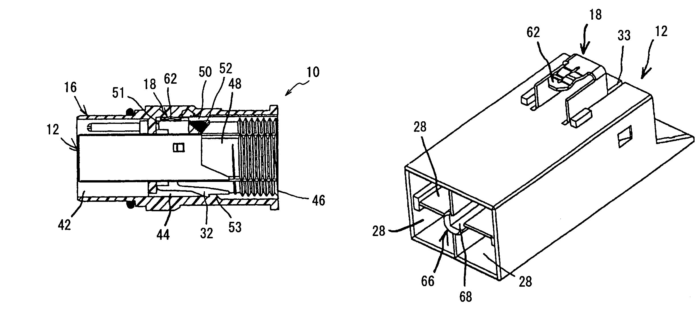
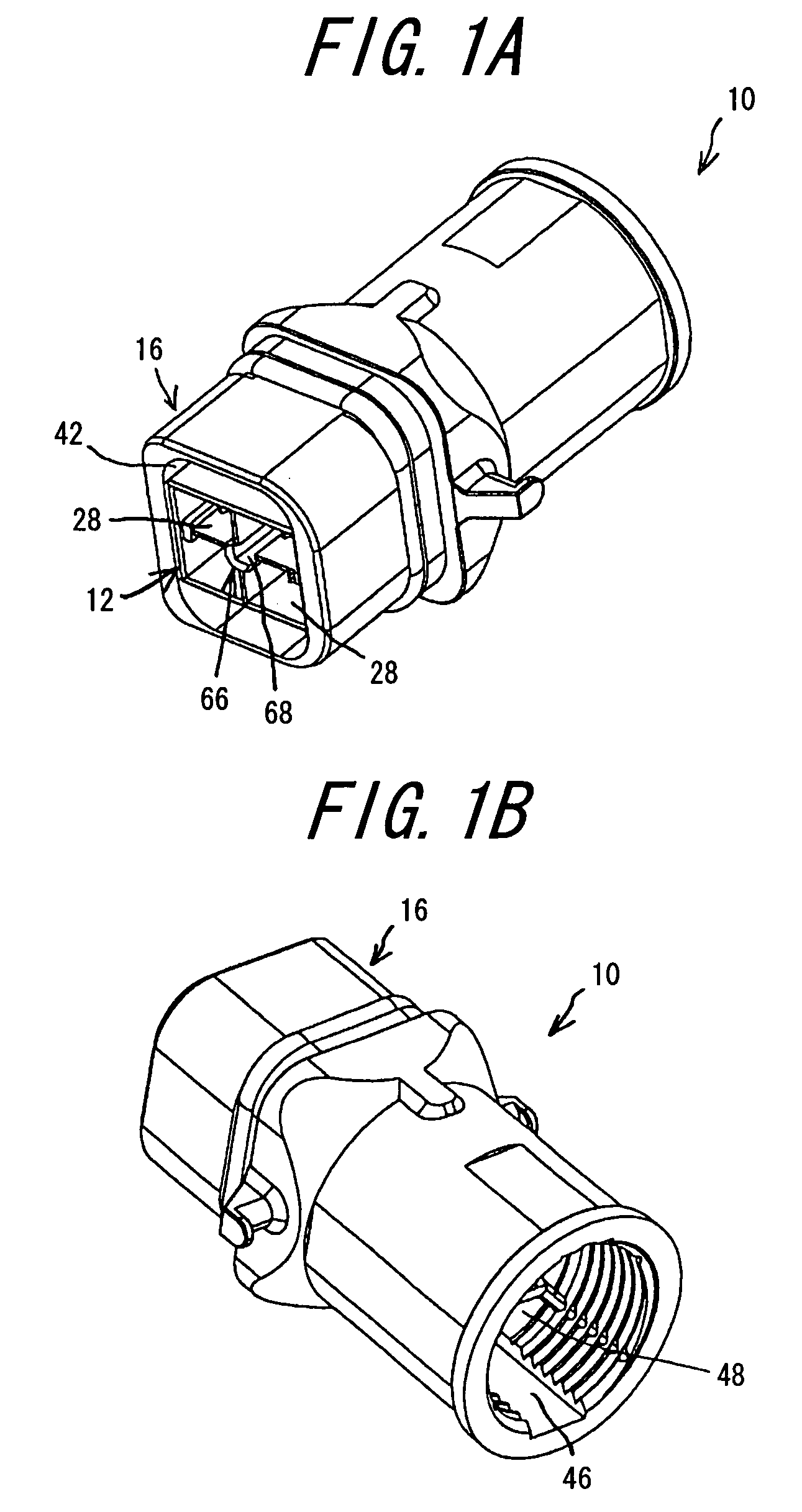
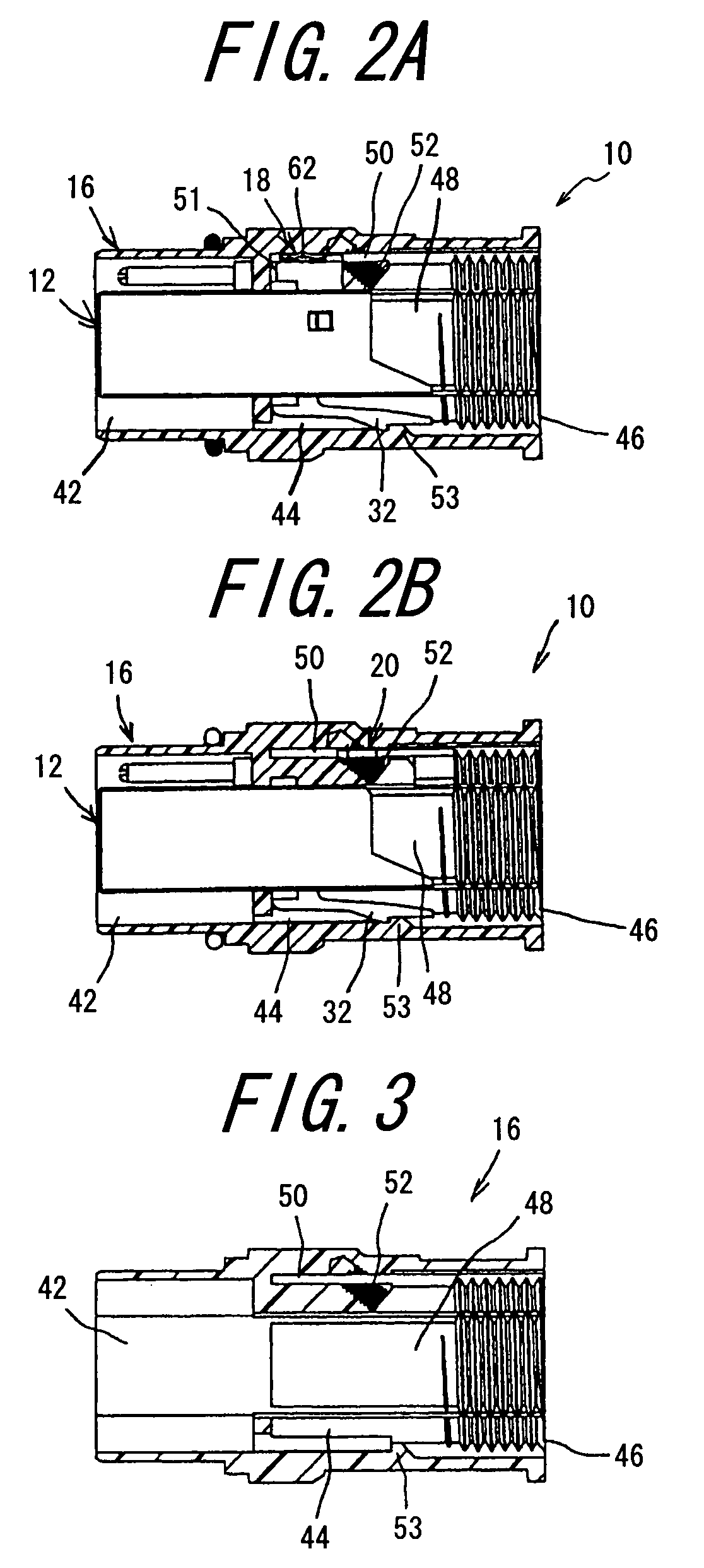
[0039]The grounding structure according to the invention and the electrical connector using the grounding structure will be explained with reference to FIG. 1A to FIG. 10B. FIG. 1A is a perspective view of the electrical connector viewed from the fitting portion, while FIG. 1B is a perspective view of the electrical connector viewed from the connection portion. FIG. 2A is a longitudinal-sectional view of the electrical connector in the case using one contact for grounding, and FIG. 2B is a longitudinal-sectional view of the electrical connector in the case using a separate ground terminal. FIG. 3 is a longitudinal-sectional view of a shell. FIG. 4A is a perspective view of a housing having a ground lug, while FIG. 4B is a sectional view of the housing. FIG. 5A is a perspective view of a housing not having a ground lug, while FIG. 5B is a sectional view of the housing. FIG. 6 is a perspective view of a contact, and FIG. 7 is a perspective view of a ground lug. FIG. 8 is a perspective...


PUM


Abstract

A grounding structure is provided in an electrical connector, which includes contacts, a housing, a shell, and a ground terminal or a ground lug. The shell has a through-hole communicating with a fitting groove, an installing groove, and a connection portion groove, and the through-hole has an inserting groove into which the ground terminal is inserted, a screw portion for holding the ground terminal, a spacing groove for avoiding any interference with the ground lug integrally mounted on the housing, and an engaging portion to engage a locking portion of the housing. Both the ground lug and the ground terminal are constructed to become electrically conductive with the same shell, respectively, so that grounding is effected by either of the ground lug integrally mounted on the housing and the separately provided ground terminal. It is thus possible to select one contact or the separate ground terminal with respect to the same shell for grounding.

Description

BACKGROUND OF THE INVENTION[0001]This invention relates to an earthing or grounding structure enabling both a ground terminal and a ground lug to be in continuity even with the same shell structure for grounding, and more particularly to an electrical connector using the grounding structure for use in machine tools, robots and the like.[0002]A commonly used electrical connector at least includes a plurality of contacts, a housing for holding the contacts, and a shell for holding the housing. Moreover, said electrical connector has an earthing or grounding structure for causing a ground terminal or ground lug to be in continuity with said shell for connecting a protection circuit as a safety measure. An earthing (i.e., grounding) structure has been disclosed in the following Patent Literature 1 or the like.[0003]Patent Literature 1[0004]Claim 1 of Japanese Patent Application Publication No. H7-82,889 (1995) has disclosed a waterproof connector characterized comprising a shell, a rubb...

Claims


Application Information

Patent Timeline
Patent Type & Authority Patents(United States)
IPC IPC(8): H01R4/66
CPCH01R13/506H01R13/6453H01R13/65802H01R13/6581
Inventor TSURUMI, MASAHIKO
Owner DDK LTD
Why Eureka
Try Eureka