Vibration damping device, in particular for an electric hand machine tool, and a transmission equipped with such a vibration damping device

a technology of vibration damping and electric hand machine tools, which is applied in the direction of hoisting equipment, manufacturing tools, portable power-driven tools, etc., can solve the problem of practically unlimited service life and achieve the effect of advantageously increasing the achievable damping ratio and small cross-section

Inactive Publication Date: 2009-03-31
ROBERT BOSCH GMBH
View PDF15 Cites 18 Cited by
  • Summary
  • Abstract
  • Description
  • Claims
  • Application Information

AI Technical Summary

Benefits of technology

[0005]The present invention proposes a vibration damping device, in particular for reducing powertrain vibrations in an electric hand machine tool, which has a rotation element that can be connected to a drive shaft in a frictionally engaging manner; the rotation element has at least one chamber filled with a pourable or fluid material capable of absorbing vibration energy.
[0008]The vibration damping device is simply designed, takes up only a small amount of space, and can be inexpensively produced since it does not require heavy-duty materials. Another advantage is that the vibration damping device can also be subsequently integrated easily and without great expense into any hand machine tool, for example it can also be integrated into a compressed air tool and in particular, can be integrated into an electric hand machine tool. The installation of the vibration damping device can be easily incorporated into an existing assembly process. The vibration damping device can be used as a separate component or can be embodied in a suitable location in the form of a transmission component, in particular a gear.
[0011]For cost reasons, it is preferable for the rotation element of the vibration damping device to be embodied as rotationally symmetrical. This simply and simultaneously prevents the vibration damping device from introducing any additional imbalance into the system. It is advantageous for the rotation element to be embodied as annular or disk-shaped, with a central opening to accommodate the drive shaft. This design allows the vibration damping device to be easily attached to a drive shaft. It is also possible to retrofit devices. The drive shaft can also be attached to the rotation element in a form-locked manner.
[0013]In another advantageous embodiment form, the chamber is embodied in the form of an annular cavity in the rotation element. An annular damping element that can move freely in the fluid is inserted into this chamber. To this end, the damping element, while having the same annular radius as the cavity, has a smaller cross-section than it. This embodiment form makes it possible to use the maximum size of damper mass without causing additional imbalance.
[0016]The chamber of the vibration damping device is advantageously integrated into an output gear of the transmission, in particular embodied in the form of a crown gear. Due to the existing space or volume of the crown gear, it is particularly easy to integrate the vibration damping device into the transmission in this location. This also makes it possible to retrofit an already existing transmission with the damping device.

Problems solved by technology

Its service life is therefore practically unlimited.
If an impact occurs during rotation, then this is damped by virtue of the fact that the pourable or fluid material counteracts the impact due to its inertia.

Method used


Image

  • Vibration damping device, in particular for an electric hand machine tool, and a transmission equipped with such a vibration damping device
  • Vibration damping device, in particular for an electric hand machine tool, and a transmission equipped with such a vibration damping device
  • Vibration damping device, in particular for an electric hand machine tool, and a transmission equipped with such a vibration damping device

Examples


Embodiment Construction

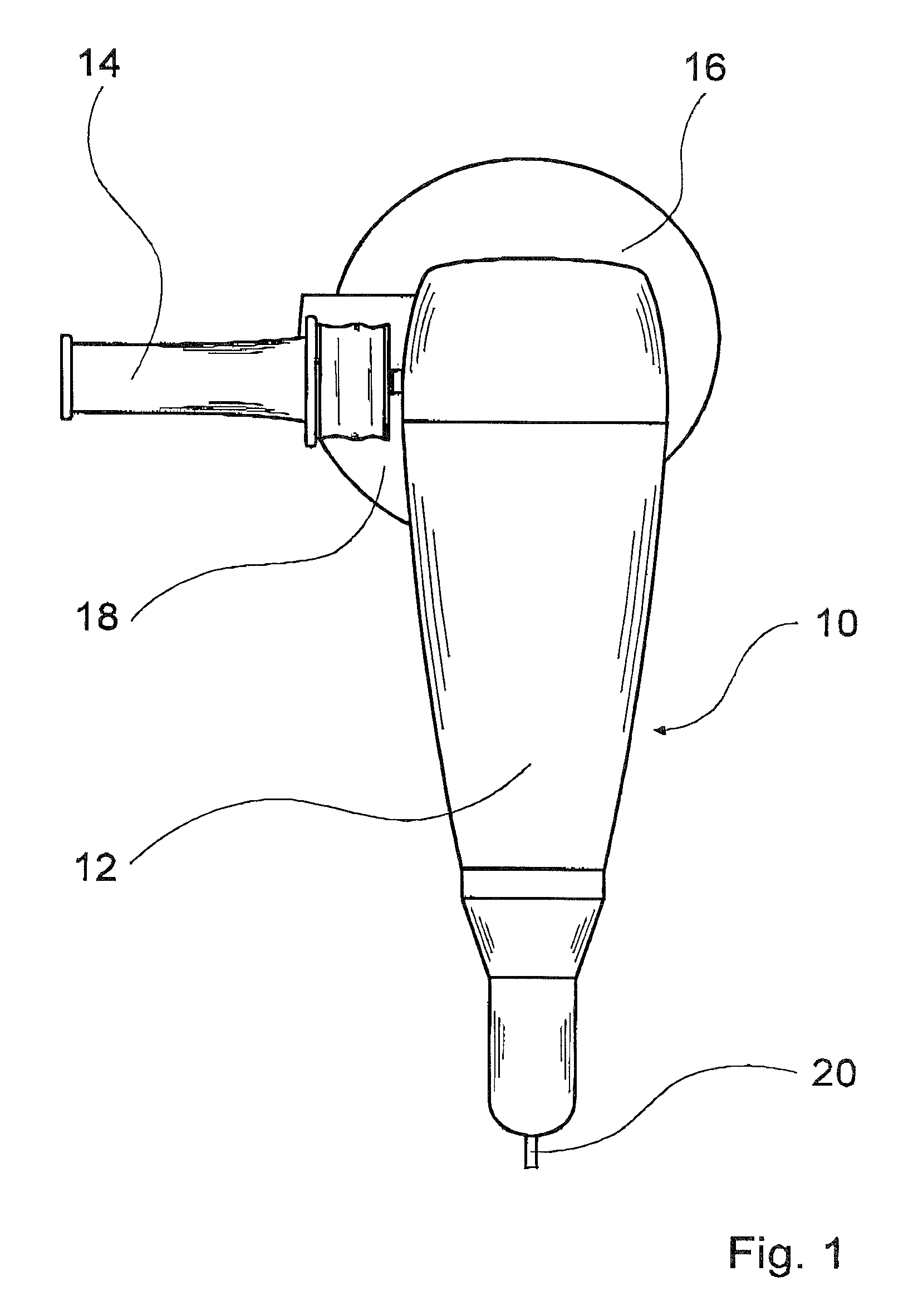
[0024]FIG. 1 shows a simplified depiction of a right angle grinder 10 as an example of an electric hand machine tool. The right angle grinder 10 has a housing 12 that contains the electric drive motor; a handle 14 for guiding the device during operation is attached to the side of the housing 12. At the front end of the housing 12, the output spindle—not visible here—protrudes at a 90° angle in relation to the longitudinal axis of the housing and is attached to a grinding disk 16. In order to protect the operator from flying particles such as dust, shavings, or sparks, a safety guard 18 is mounted over the grinding disk 16 on the handle side of the housing 12. To supply electrical energy, a power cable 20 is integrated into the rear end of the housing 12.

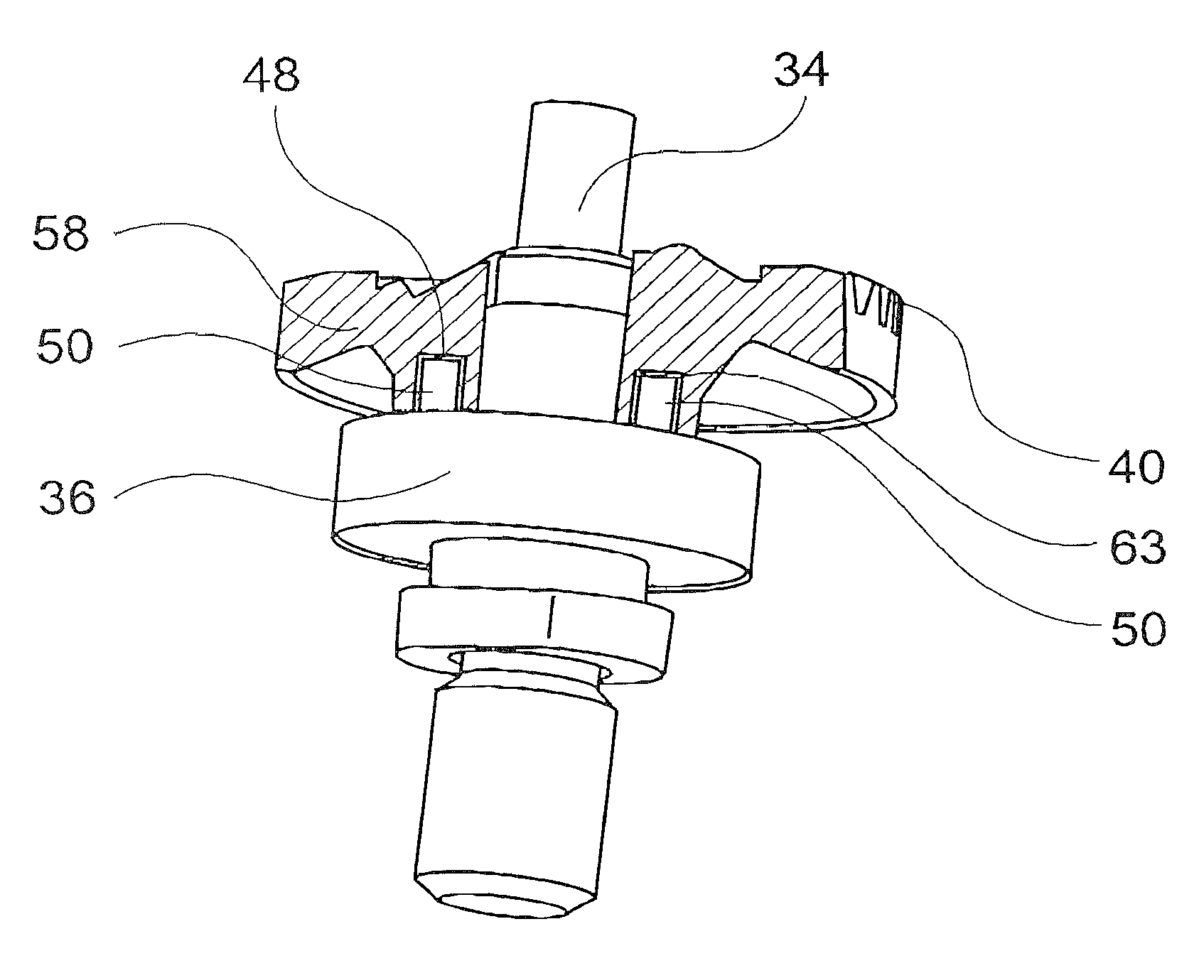
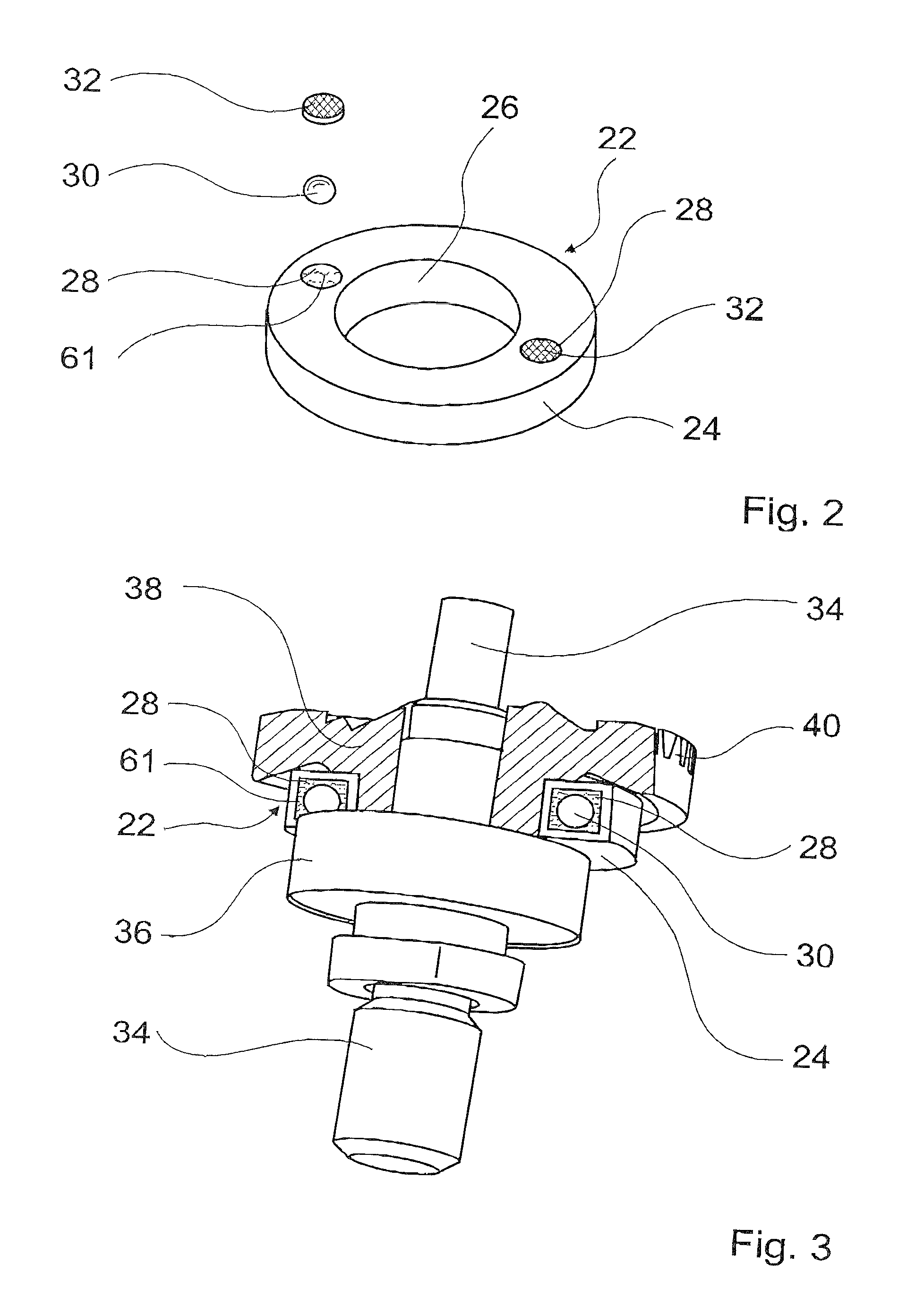
[0025]FIG. 2 shows an exploded view of a vibration damping device 22 in the uninstalled state. The vibration damping device 22 has an annular rotation element 24 with a central opening 26. By means of the central opening 26, the rota...


PUM


Abstract

A vibration damping device has a rotation element connectable to a drive shaft in a frictional, nonpositive way and provided with at least one chamber filled with a material selected from the group consisting of a pourable material and a fluid material and capable of absorbing vibration energy.

Description

BACKGROUND OF THE INVENTION[0001]The present invention relates to a vibration damping device, in particular for damping powertrain vibrations in an electric hand machine tool. The present invention also relates to a transmission, in particular for an electric hand machine tool, equipped with such a vibration damping device.[0002]A transmission of an electric hand machine tool contains gears with a helical or threaded gearing, which are usually sintered for cost reasons. Cut gears, whose production costs are high, are only used for high-quality units that require a high degree of running smoothness. In comparison to cut gears, sintered gears have higher manufacture-induced tolerances. In a transmission, this can lead to additional oscillations and vibrations in the power train.[0003]Prior inventions have already proposed inserting spring elastic damping elements, in particular made of rubber or a rubber-like material, between the drive gear and the output shaft to reduce power train ...

Claims


Application Information

Patent Timeline
Patent Type & Authority Patents(United States)
IPC IPC(8): B24B41/00B24B23/02B25F5/00F16F15/173F16H55/14
CPCB24B23/028B24B41/007B25F5/006F16H55/14F16F15/173Y10T74/2122Y10T464/50F16F15/10
Inventor STIERLE, PETERWIKER, JUERGEN
Owner ROBERT BOSCH GMBH
Why Eureka
Try Eureka