
Method for fluid injector

a technology of injector and fluid, which is applied in the direction of printed circuit assembly, printed circuit manufacturing, printing, etc., can solve the problem that the injection direction of fluid cannot be consistent, and achieve the effect of improving efficiency and li

Inactive Publication Date: 2009-04-07
BENQ CORP
View PDF10 Cites 1 Cited by
  • Summary
  • Abstract
  • Description
  • Claims
  • Application Information

AI Technical Summary

Benefits of technology

The design enhances the structural strength and heat dissipation of the fluid injector, ensuring consistent fluid injection direction and improved operational efficiency by effectively managing heat generated by the heaters.

Problems solved by technology

Furthermore, since the thickness of the structure layer 12 is insufficient, the injection direction of injecting fluid cannot be consistent.

Method used


Image

  • Method for fluid injector
  • Method for fluid injector
  • Method for fluid injector

Examples


first embodiment

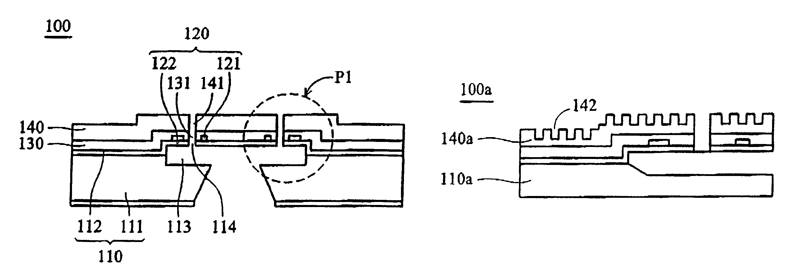
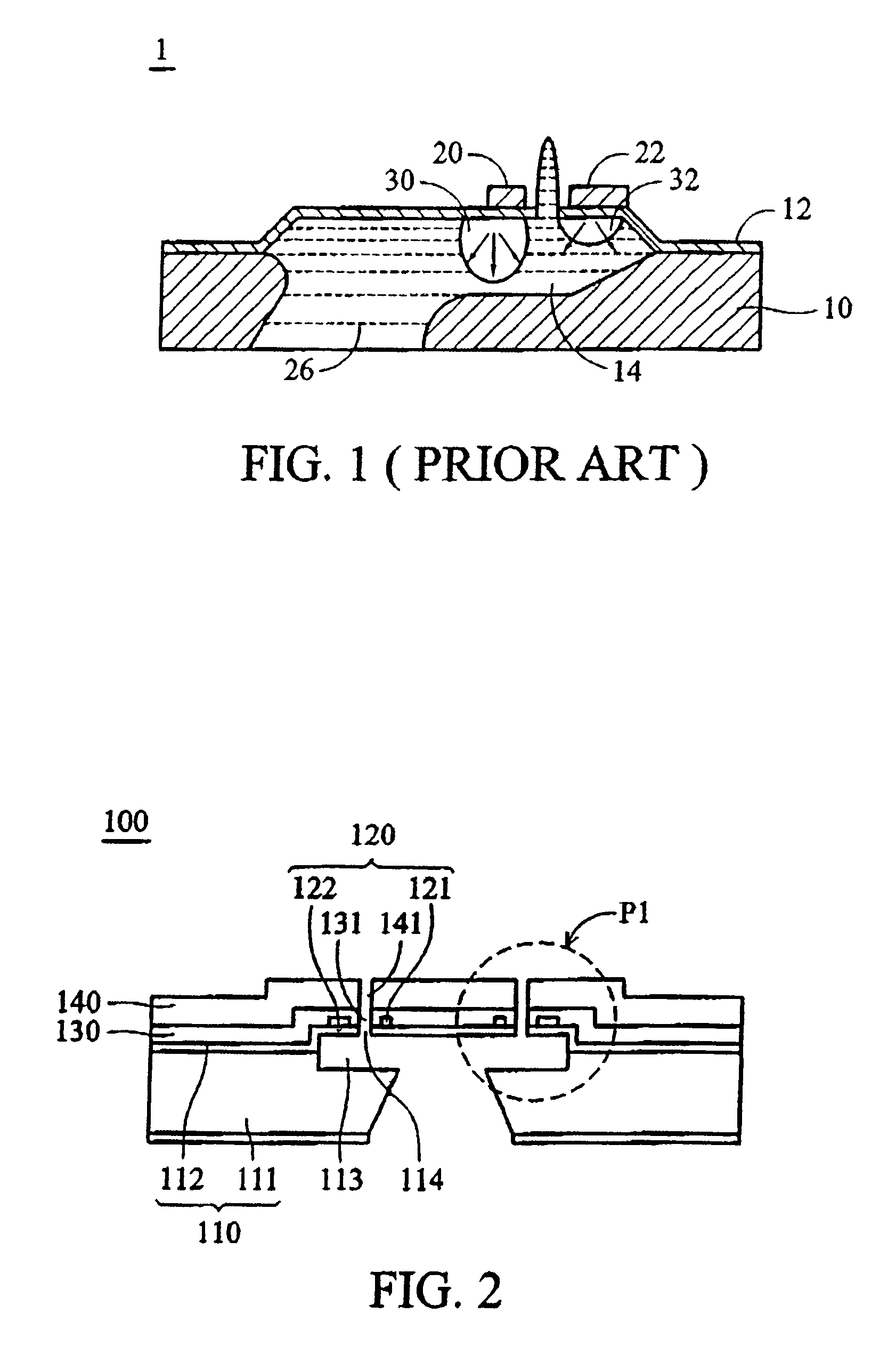
[0033]Referring to FIG. 2, a fluid injector 100, as disclosed in a first embodiment of this invention, is shown. In this embodiment, the fluid injector 100 comprises a base 110, a first through hole 114, a bubble generator 120, a passivation layer 130, and a metal layer 140.

[0034]The base 110 includes a silicon substrate 111 and a structural layer 112. The structural layer 112 is disposed on the silicon substrate 111. A chamber 113 is formed between the silicon substrate 111 and the structural layer 112. The first through hole 114 is formed in the structural layer 112, and communicates with the chamber 113.

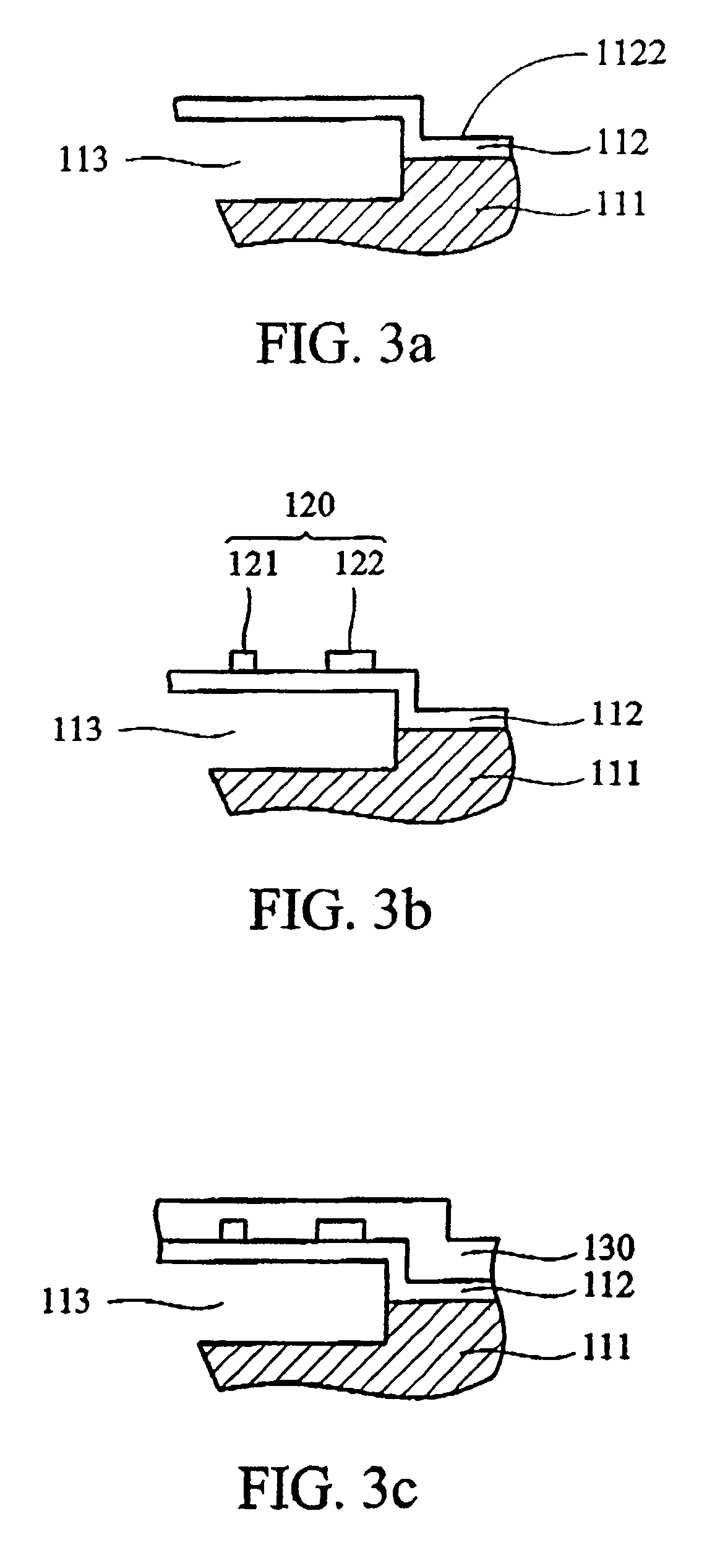
[0035]The bubble generator 120 is disposed on a surface 1122 of the structural layer 112 as shown in FIG. 3a. The bubble generator 120 is located near the first through hole 114 and outside the chamber 113 of the base 110. In this embodiment, the bubble generator 120 includes a first heater 121 and a second heater 122. Like the heaters shown in FIG. 1, the first heater 120 generat...

second embodiment

[0047]FIG. 5 is a schematic view of a fluid injector 100d as disclosed in a second embodiment of this invention. The difference between the fluid injector 100d of this embodiment and that of the first embodiment is that the bubble generator 120 comprises only one heater 120d. The other components of this embodiment are the same as those of the first embodiment; therefore, their description is omitted.

[0048]Since the fluid injector of this embodiment is also provided with the metal layer, it can obtain the same effect as the first embodiment. That is, the structural strength of the whole fluid injector can be enhanced, and the heat remaining in the bubble generator can be quickly transferred away, and the injecting direction of the fluid can be more definite.

third embodiment

[0049]Referring to FIG. 6, a fluid injector 100e, as disclosed in a third embodiment of this invention, is shown. In this embodiment, the fluid injector 100e comprises a silicon substrate 111e, a structural layer 112e, a first through hole 114, a bubble generator 120, a passivation layer 130e, a metal layer 140, and a second through hole 141. It is noted that the first through hole 114, the bubble generator 120, and the second through hole 141 are the same as those of the first embodiment; therefore, their description is omitted, and their reference numbers are identical to those of the first embodiment.

[0050]The difference between this embodiment and the first embodiment are that in this embodiment, a third through hole 1121e is formed in the structural layer 112e as shown in FIG. 7a, and a fourth through hole 132e is formed in the passivation layer 130e as shown in FIG. 7c. The fourth through hole 132e corresponds to the third through hole 1121e, and the metal layer 140e is direct...


PUM

PropertyMeasurementUnit
diameteraaaaaaaaaa
adhesionaaaaaaaaaa
densityaaaaaaaaaa

Abstract

A fluid injector and method of manufacturing the same. The fluid injector comprises a base, a first through hole, a bubble generator, a passivation layer, and a metal layer. The base includes a chamber and a surface. The first through hole communicates with the chamber, and is disposed in the base. The bubble generator is disposed on the surface near the first through hole, and is located outside the chamber. The passivation layer is disposed on the surface. The metal layer defines a second through hole, and is disposed on the passivation layer outside the chamber. The second through hole communicates with the first through hole.

Description

CROSS-REFERENCE TO RELATED APPLICATIONS[0001]This patent application is a divisional application of U.S. Ser. No. 10 / 618,928, filed on Jul. 11, 2003, now U.S. Pat. No. 7,040,740, which claims priority to Taiwanese Application No. 91115599, filed on Jul. 12, 2002.BACKGROUND OF THE INVENTION[0002]1. Field of the Invention[0003]The invention relates to a fluid injector and a method of manufacturing the same; in particular, a fluid injector with enhanced efficiency and lifetime.[0004]2. Description of the Related Art[0005]Normally, a fluid injector is applied in an inkjet printer, a fuel injector, and other devices. Among inkjet printers presently known and used, injection by a thermally driven bubble has been most successful due to its simplicity and relatively low cost.[0006]FIG. 1 is a conventional monolithic fluid injector 1 as disclosed in U.S. Pat. No. 6,102,530. A structural layer 12 is formed on a silicon substrate 10. A fluid chamber 14 is formed between the silicon substrate 1...

Claims


Application Information

Patent Timeline
Patent Type & Authority Patents(United States)
IPC IPC(8): B21D53/76B41J2/04
CPCB41J2/14137Y10T29/49126Y10T29/49401Y10T29/4913Y10T29/49128
Inventor HU, HUNG-SHENGCHEN, WEI-LINLEE, IN-YAOHSU, TSUNG-PINGCHOU, CHUNG-CHENGWU, SHANGSHI
Owner BENQ CORP
Learn More