
System and method for illuminating a target

a target and target technology, applied in the field of optics, can solve the problems of increasing the size of the system, deficient image, and insufficient preservation of the etendue of the light source, so as to reduce the divergence of light beams, reduce the size, cost, and alignment sensitivity of the system

Active Publication Date: 2011-01-11
TEXAS INSTR INC
View PDF2 Cites 0 Cited by
  • Summary
  • Abstract
  • Description
  • Claims
  • Application Information

AI Technical Summary

Benefits of technology

The present invention provides a system for illuminating a target using a light source and a lens. The lens is positioned between the light source and the target. The lens changes the divergence of the light beams emitted from the light source to a lower value, while also satisfying the sine condition without removing spherical aberrations. This helps to preserve the etendue of the light source, even if the optical quality of the light beams is deficient. The lens separation from the light source increases the efficiency and lifespan of the light source. Additionally, a combiner may include a collimating lens with a single optically active surface, which reduces the size, cost, and alignment sensitivity of the system.

Problems solved by technology

These systems, however, typically do not adequately preserve the etendue of the light source, yielding a deficient image.
Certain collimators, however, increase the size of the system.
As a result, the system may be inappropriate for certain applications, such as cell phones and projectors.

Method used


Image

  • System and method for illuminating a target
  • System and method for illuminating a target
  • System and method for illuminating a target

Examples


Embodiment Construction

[0012]Embodiments of the present invention and its advantages are best understood by referring to FIGS. 1A through 3 of the drawings, like numerals being used for like and corresponding parts of the various drawings.

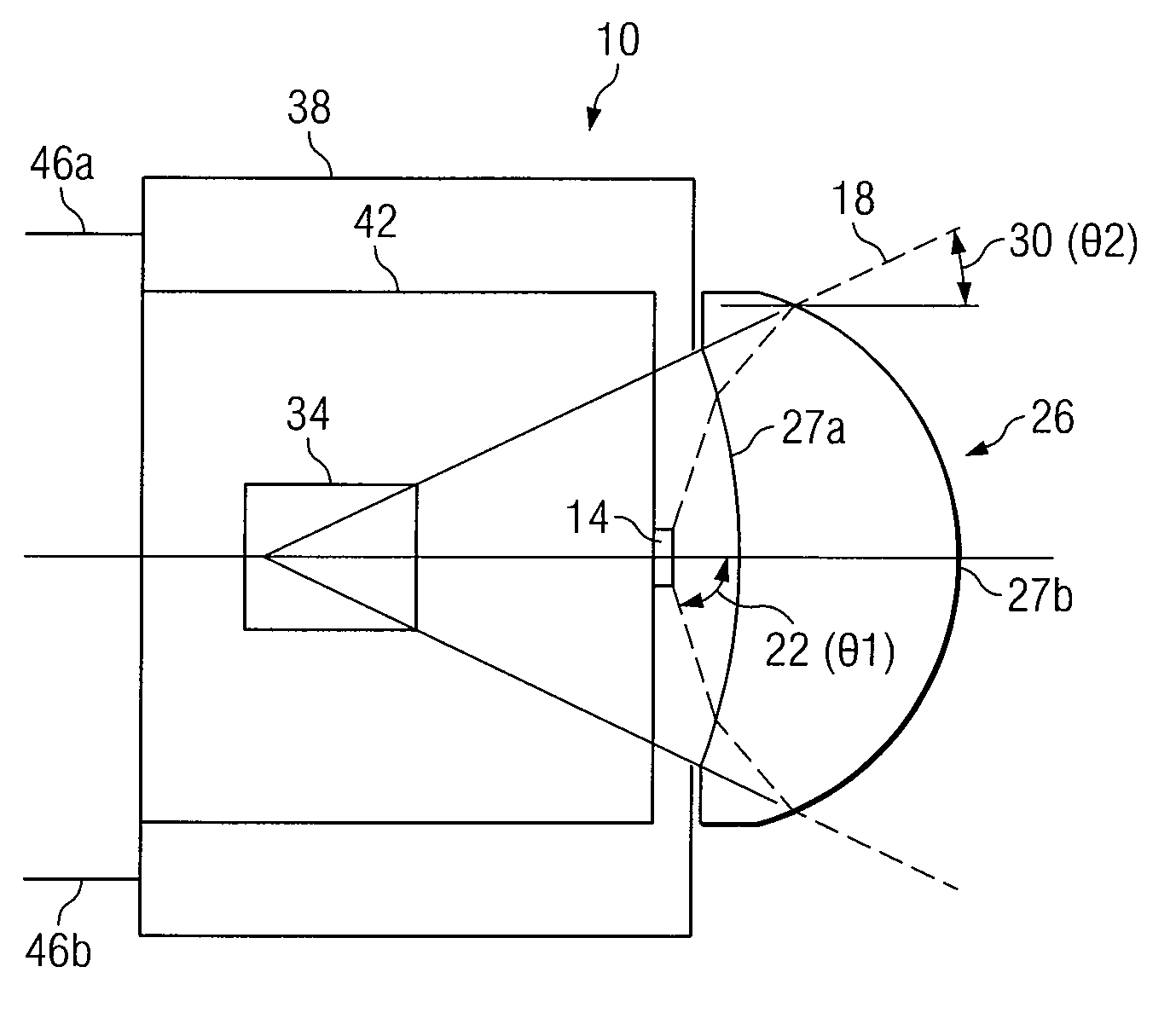
[0013]FIG. 1A illustrates an example of one embodiment of a system 10 that may illuminate a target. In the embodiment, system 10 includes a lens 26 that may be configured to reduce the divergence of one or more light beams 18 received from a light source 14. Reducing the divergence of light beams 18 may preserve the etendue of light source 14, enabling light beams 18 to provide a sharper image when illuminating a target. Additionally, lens 26 may be further configured to substantially satisfy the sine condition without removing spherical aberrations from light beams 18. In a further embodiment, lens 26 may be optically separated from light source 14, which may increase the efficiency and life time of light source 14.

[0014]According to the illustrated embodiment, system 1...


PUM


Abstract

According to one embodiment of the present invention, a system for illuminating a target includes a light source configured to emit one or more light beams with a first divergence. The system further includes a lens separated from the light source. The lens is configured to substantially satisfy the sine condition without removing spherical aberrations from the one or more light beams. The lens is further configured to receive the one or more light beams with the first divergence. The lens is further configured to change the first divergence of the one or more light beams to a second divergence. The second divergence is less than the first divergence. The second divergence is greater than zero. The lens is further configured to transmit the one or more light beams with the second divergence.

Description

TECHNICAL FIELD OF THE INVENTION[0001]This invention relates generally to the field of optics and more specifically to a system and method for illuminating a target.BACKGROUND OF THE INVENTION[0002]In certain systems, light beams emitted from a light source pass through one or more lenses to illuminate a target. These systems, however, typically do not adequately preserve the etendue of the light source, yielding a deficient image.[0003]Additionally, a collimator may be used in the systems to collimate the light beams. Certain collimators, however, increase the size of the system. As a result, the system may be inappropriate for certain applications, such as cell phones and projectors.SUMMARY OF THE INVENTION[0004]According to one embodiment of the present invention, a system for illuminating a target includes a light source configured to emit one or more light beams with a first divergence. The system further includes a lens separated from the light source. The lens is configured t...

Claims


Application Information

Patent Timeline
Patent Type & Authority Patents(United States)
IPC IPC(8): G02B27/02G02B9/00
CPCG02B27/102G02B19/0014G02B19/0047G02B27/145G02B27/0961
Inventor DESTAIN, PATRICK RENEBARTLETT, TERRY ALAN
Owner TEXAS INSTR INC
Learn More