Wire stripper which can be automatically adapted to different conductor cross sections

a technology of automatic adaptation and cross section, which is applied in the direction of cable removal/armouring equipment, cable installation equipment, electrical equipment, etc., can solve the problems of inability to adapt to varying thicknesses of insulation materials, limited adaptation to wire gauges, and inability to prevent conductor damage, etc., to achieve the effect of preventing damage to the conductor and being easy to repla

Active Publication Date: 2009-04-07
RENNSTEIG WERKZEUGE
View PDF9 Cites 28 Cited by
  • Summary
  • Abstract
  • Description
  • Claims
  • Application Information

AI Technical Summary

Benefits of technology

[0013]In another useful embodiment of the invention, a slight longitudinal displacement of the sliding-wedge surfaces with respect to each other is achieved by the shape of the second surface. This causes a slight opening of the plier jaws as the cutter jaws move. This can compensate for irregularities in the cable to be stripped, thus preventing damage to the conductors.
[0014]It is further advantageous to attach the cutter blades to the cutter jaws so that they may be removed. The cutter blades are preferably screwed onto the fron

Problems solved by technology

For this, the most important issue is that the sheathing at the end of the cable, and of the individual conductors, may be removed in the contact area cleanly and at the proper length.
Improper operation or adjustment always presented a hazard of conductor damage.
Limited adaptation to the wire gauge is achieved by means of the resista

Method used


Image

  • Wire stripper which can be automatically adapted to different conductor cross sections
  • Wire stripper which can be automatically adapted to different conductor cross sections
  • Wire stripper which can be automatically adapted to different conductor cross sections

Examples


Embodiment Construction

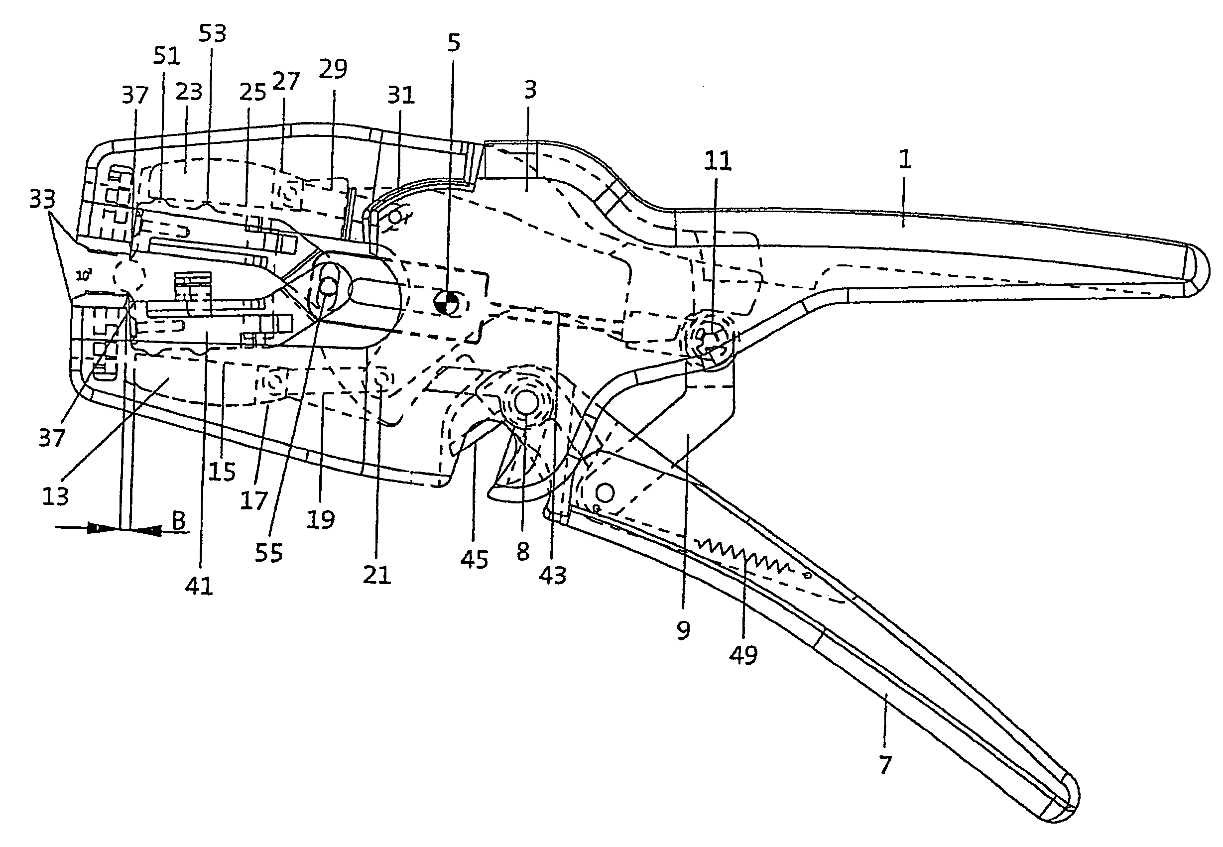
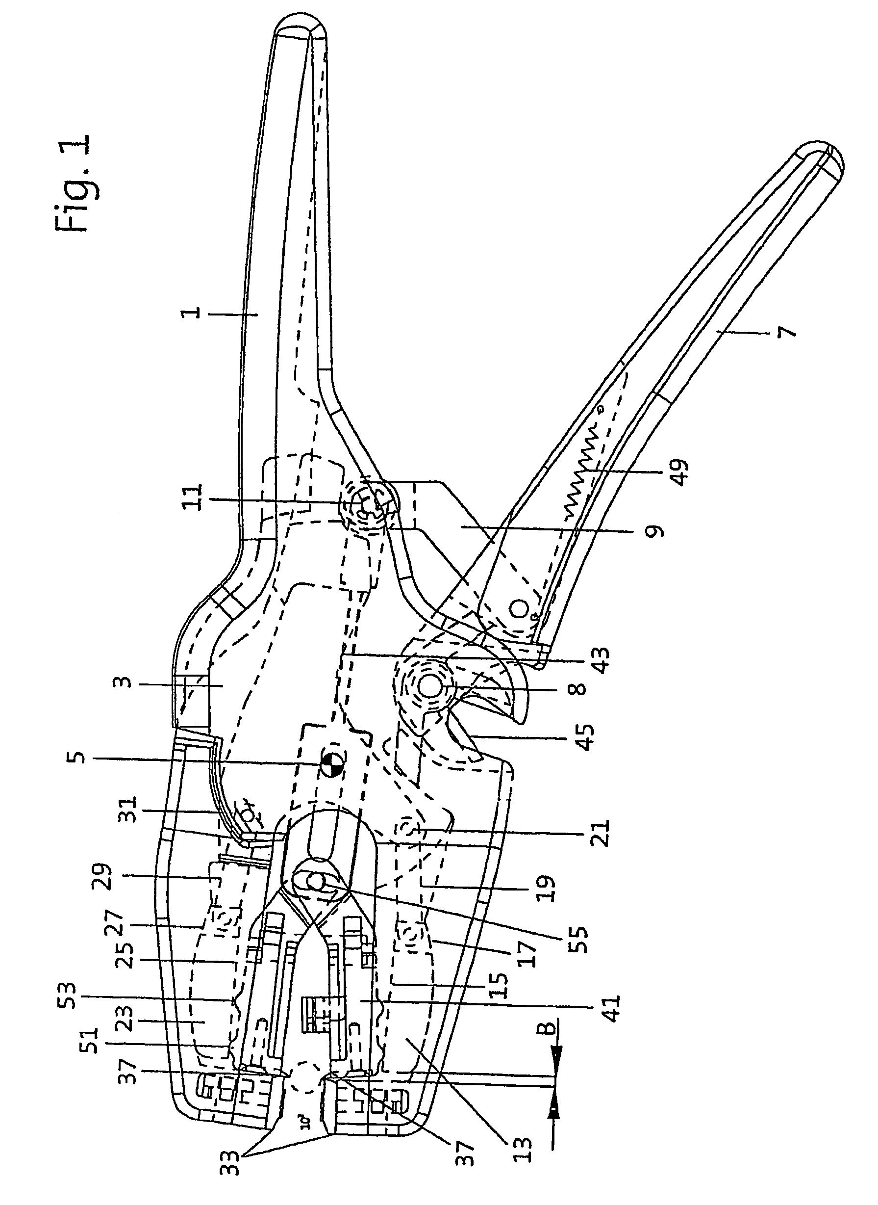
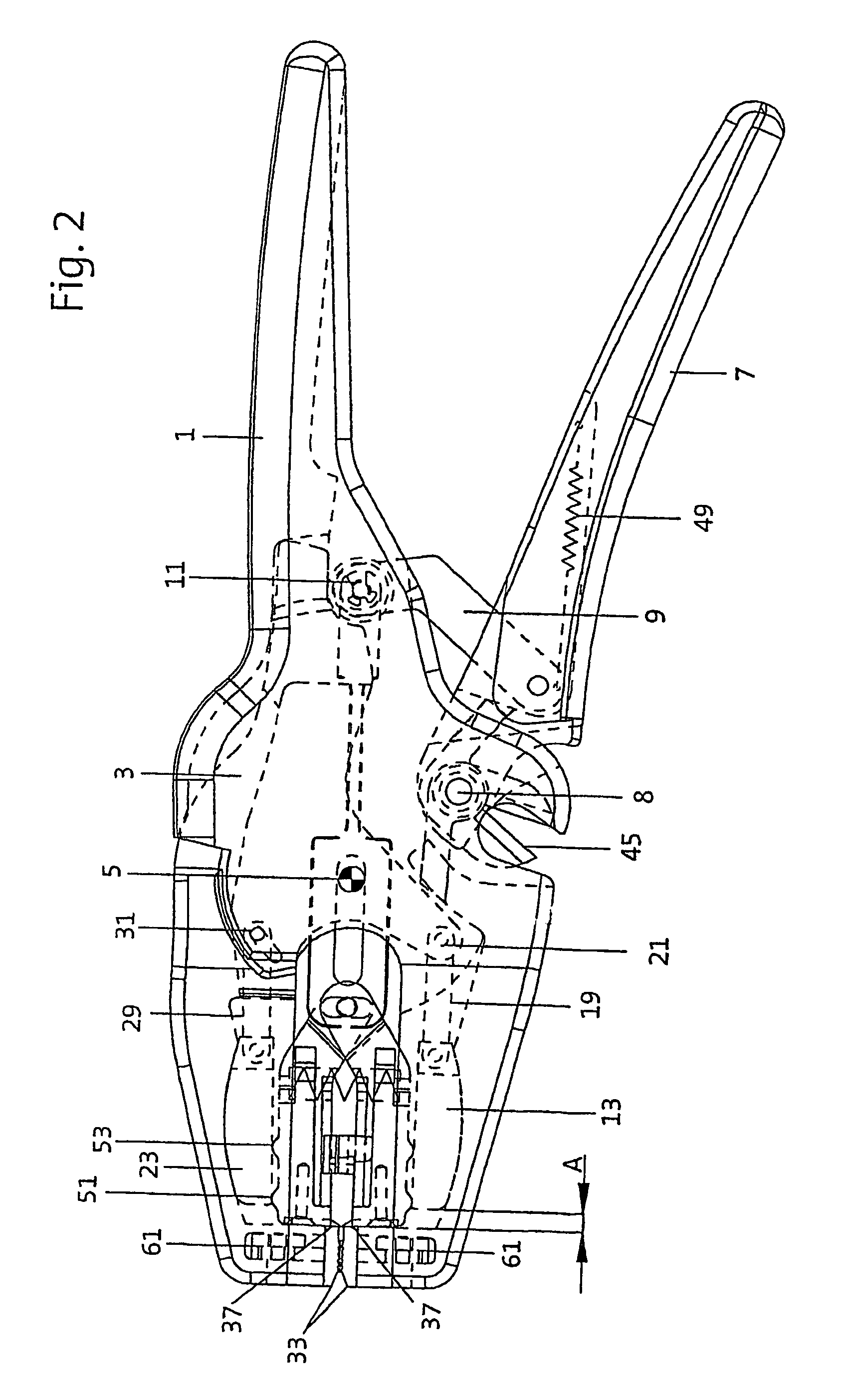
[0023]FIG. 1 shows a wire-stripping plier based on the invention with opened jaws in an overall view. The wire-stripping plier includes a first plier arm 1 and a jaw part 3, which possess a common pivot point 5. A second plier arm 7 that is connected via a lever pivot axis 8 with the first plier arm acts via a link 9 with a roller 11 on the jaw part 3 so that the plier jaws are also closed by a closing movement of the plier arms.

[0024]A first sliding wedge 13 with a sliding-wedge surface 15 facing the plier jaw opening is located in a recess in the first plier arm, and a second surface 17 is also in the recess. The first sliding wedge 13 is connected with the jaw part 3 via a first coupling rod. A first pin 21 serves to secure the first coupling rod 19 in the jaw part 3.

[0025]A second sliding wedge 23 is mounted within a recess in the jaw part 3. It possesses a sliding-wedge surface 25 facing the plier jaw opening and a second surface 27 in the recess.

[0026]The second sliding wedge ...


PUM


Abstract

The invention relates to wire-stripping pliers with an automatic adaptation to various wire gauges and insulation thicknesses that has two pairs of pivotable jaws of which the jaws of the first, outer pair are configured as gripper jaws and are pivotable by means of a first jaw arm and a jaw part about a common point, and the jaws of the other, inner pair are configured as cutting jaws with blades that cut into the insulation, and with a pull rod attached to the cutter jaws and longitudinally moveable within the jaw body providing the stripping motion that is coupled with a second plier arm. At least one sliding wedge is mounted in a recess shaped to match the sliding wedge within the first plier arm or in the jaw part, whereby a first sliding wedge facing the cutting jaws is flat and a second sliding wedge resting in the recess is so shaped that the separation between both sliding wedges at a central area of the sliding wedge diminishes toward at least one of the two sliding wedge ends. Under this configuration, opening the insulation-stripping jaws causes longitudinal displacement of the sliding wedge along with simultaneous matching of position of the sliding wedge perpendicular to the longitudinal direction that results in cutting-depth adjustment of the cutting jaws and the cutting blade attached to it.

Description

BACKGROUND OF THE INVENTION[0001]The invention relates to a wire-stripping plier with an automatic adaptation to various wire gauges and insulation thicknesses with two pairs of pivotable jaws of which the jaws of a first, outer pair are configured as gripper jaws and that are pivotable by means of a first jaw arm and a jaw part about a common point, and the jaws of the other, inner pair that are configured as cutting jaws with blades that cut into the insulation, and with a pull rod attached to the cutter jaws and longitudinally moveable within the jaw body providing the stripping motion that is coupled with a second plier arm.[0002]There are many pliers and similar hand tools used to strip the insulation from electric cables. Compared with traditional cable cutters, adjustable or pre-set wire-stripping pliers offer improved safety for the user and for the cable material. In order to maintain a high-quality connection, it must be ensured that the electrical conductor (single or mul...

Claims


Application Information

Patent Timeline
IPC IPC(8): H02G1/12
CPCH02G1/1204H02G1/1212
Inventor HOFMANN, HORSTWILHELM, EDGAR
Owner RENNSTEIG WERKZEUGE
Why Eureka
Try Eureka