Container system

a container and fluid technology, applied in the direction of positive displacement liquid engines, lubricant transfer, instruments, etc., can solve the problems of inconvenient means of monitoring, no means for determining the fluid level in the container, and no suitable monitoring means for the conventional system

Active Publication Date: 2009-04-07
LINCOLN INDUSTRIES CORP
View PDF15 Cites 14 Cited by
  • Summary
  • Abstract
  • Description
  • Claims
  • Application Information

AI Technical Summary

Benefits of technology

[0008]In another embodiment, a container system of this invention comprises a container for holding a viscous fluid, and a follower in the container adapted to move up and down in the container in response to a change in a level of fluid in the container. A first vertical member in the container extends through a first opening in the follower. The system includes a first seal assembly comprising a seal surrounding the first vertical member for sealing the first opening in the follower. The seal is movable in a generally horizontal plane relative to the follower plate to prevent binding of the first vertical member in the first opening as the follower moves in the container.

Problems solved by technology

Conventional systems have not been provided with suitable means for monitoring the level of grease in a container.
However, until the switch is activated, there is no means for determining the level of fluid in the container, short of removing the lid.
Further, when the container is refilled, there is no convenient means for determining when the container is full except by overflow of lubricant from the container, or by other means which are not convenient.

Method used


Image

  • Container system
  • Container system
  • Container system

Examples


Embodiment Construction

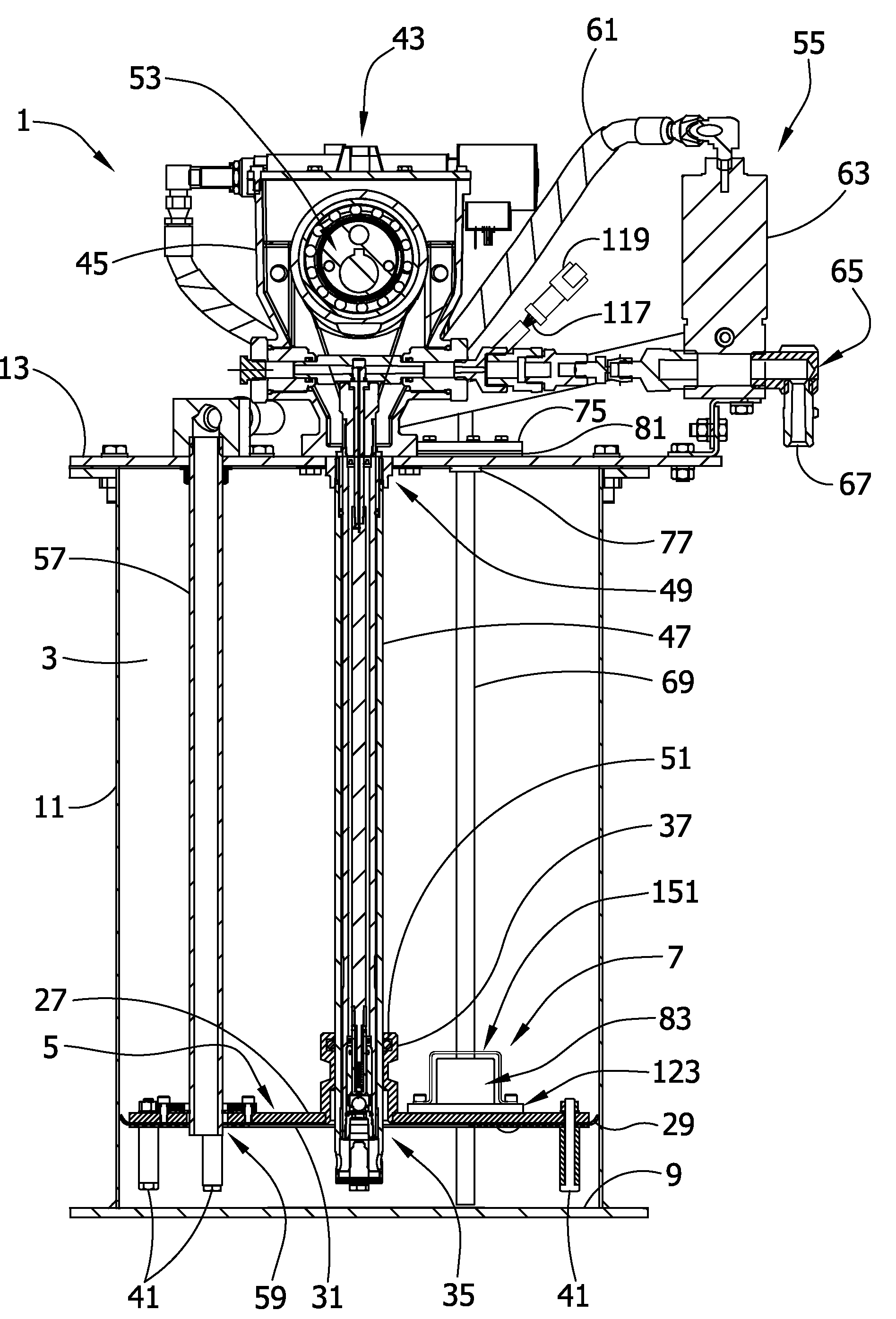
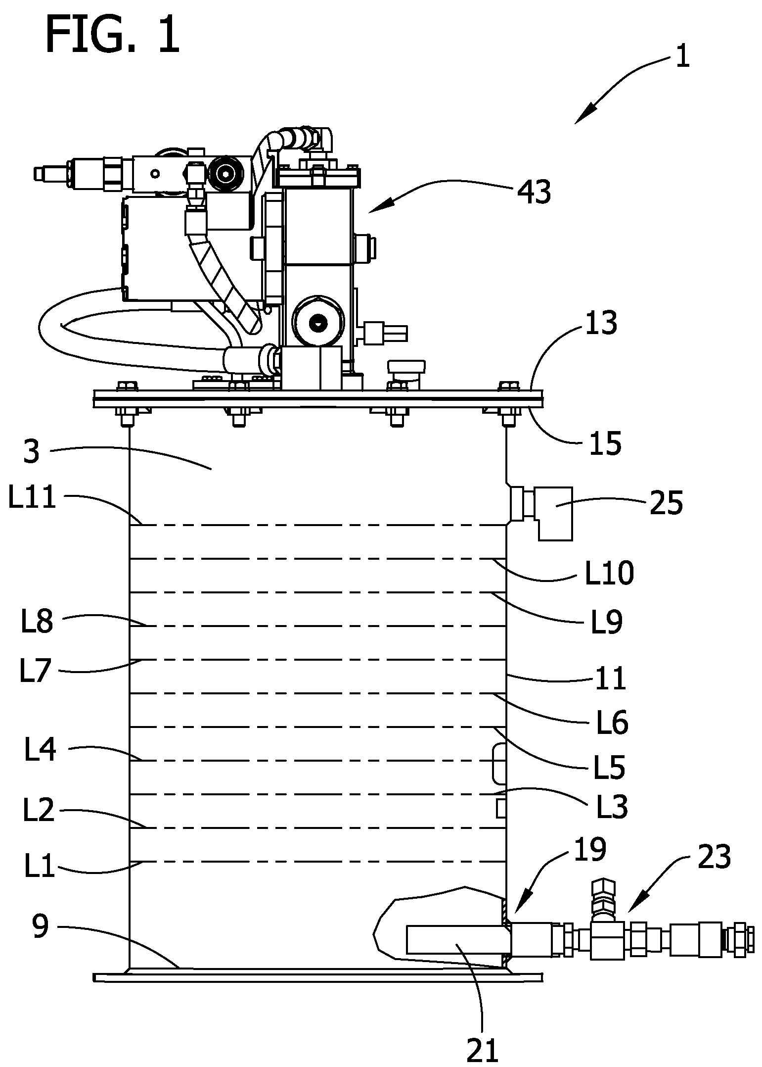
[0022]Referring now to the drawings, and first more particularly to FIG. 1, one embodiment of a container system 1 of the present invention is indicated in its entirety by the reference number 1. As illustrated in FIG. 3, the system 1 comprises a container 3 for holding a supply of viscous fluid, e.g., a viscous lubricant such as grease, and a follower, generally indicated at 5, positioned inside the container 3 above the lubricant. As will be understood by those skilled in this industry, the follower 5 rests on the lubricant and rises and falls inside the container as the level of lubricant changes. The container system 1 also includes a sensor assembly, generally designated 7, for sensing and signaling the level of fluid in the container. These components are described in more detail below.

[0023]Referring to FIG. 1, the container 3, sometimes referred to as a bucket, has a bottom 9, a side wall 11, and a top comprising a removable lid 13 fastened to a flange 15 around the rim of t...


PUM


Abstract

A container system of this invention includes a container for holding a fluid, a follower in the container which moves in the container in response to a change in a level of fluid in the container, and a sensor assembly for sensing the level of fluid in the container. The sensor assembly is especially (albeit not exclusively) suited for viscous fluids.

Description

BACKGROUND OF THE INVENTION[0001]This invention relates generally to container systems, and more particularly to a container system used in the delivery of viscous fluids, such as lubricants.[0002]The proper lubrication of mechanical systems requires the delivery of a suitable lubricant (e.g., grease) at regular intervals to various points of lubrication. A typical source of lubricant is a container system comprising a container filled with grease, and a follower in the container above the grease which moves up and down as the level of grease in the container rises and falls. Lubricant is pumped under pressure from the container to locations where the lubrication is needed.[0003]Conventional systems have not been provided with suitable means for monitoring the level of grease in a container. By way of example, one such system uses a switch mounted on the lid of the container, a mass which rests on the follower in the container, and a flexible line connecting the mass to the switch. ...

Claims


Application Information

Patent Timeline
Patent Type & Authority Patents(United States)
IPC IPC(8): B67D5/42B67D7/60B67D7/22
CPCB67D1/0871B67D7/16B67D7/22B67D7/66G01F23/74F16N7/385F16N19/003F16N37/00B67D7/645F16N11/00F16N11/08
Inventor KOTYK, JEFFREY M.
Owner LINCOLN INDUSTRIES CORP
Why Eureka
Try Eureka