Backlight module and reflector thereof

a backlight module and reflector technology, applied in the field of backlight modules, can solve the problems of reducing the utilization efficiency of light beams, and reducing light energy utilization efficiency, so as to improve the light distribution uniformity

Active Publication Date: 2009-04-07
TSINGHUA UNIV +1
View PDF7 Cites 44 Cited by
  • Summary
  • Abstract
  • Description
  • Claims
  • Application Information

AI Technical Summary

Benefits of technology

[0014]An embodiment of the present backlight module includes a light guide plate, a light source, a micro reflector array, and a reflector. The light guide plate includes a light input surface facing the light source, a light output surface orthogonally adjacent to the light input surface, and a reflective surface opposite to the light output surface. The light source and the emitting surface thereof both face the light input surface. The micro reflector array includes a number of micro reflectors on the light input surface. The micro reflectors, reflecting the light beams emitted from the light source, are substantially directed toward the light source and are spaced from one another by a microgap. The reflector arranged around the light source faces the light input surface of the light guide plate. The micro reflector array and the reflector are structured and arranged for cooperatively coupling a first portion of the light beams into the light input surface via any corresponding microgap and reflecting a second portion of the light beams into the light guide plate at a location distant from the light source. The reflector is thus adapted to reflect the light reflected by the micro reflector array back into the light guide plate in a manner that achieves improved light distribution uniformity.

Problems solved by technology

This phenomenon reduces light distribution uniformity.
As such, these structures can reduce a utilization efficiency of light beams.
This configuration tends to reduce the light distribution uniformity and utilization efficiency of light energy.

Method used


Image

  • Backlight module and reflector thereof
  • Backlight module and reflector thereof
  • Backlight module and reflector thereof

Examples


first embodiment

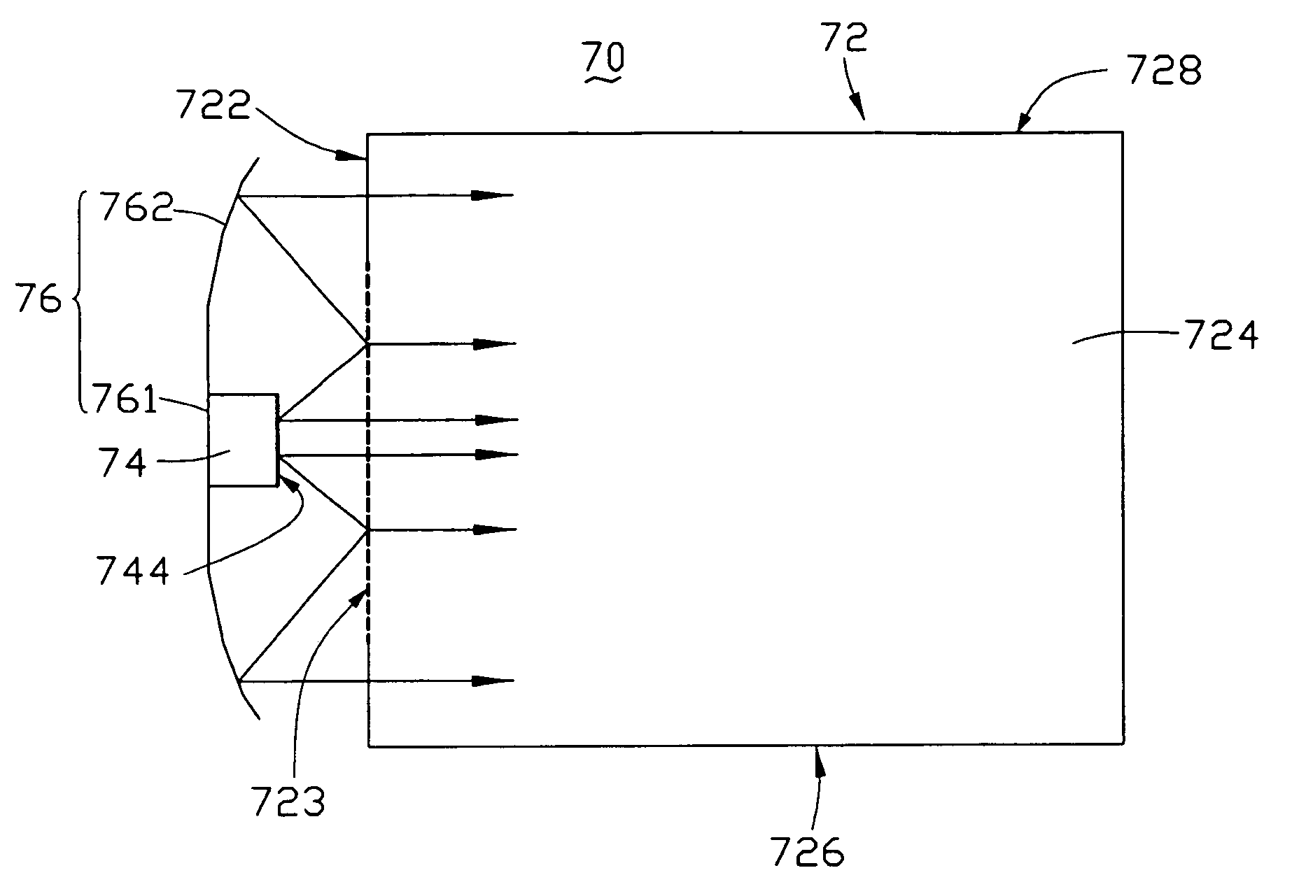
[0032]FIG. 1 shows a backlight module 70 of a The backlight module 70 includes a light guide plate 72, a light source 74, a micro reflector array 723, and a reflector 76.

[0033]The light guide plate 72 includes a light input surface 722 located on a sidewall thereof, a light output surface 724 adjacent and orthogonal to the light input surface 722, a reflective surface (not labeled) opposite to the light output surface 724, and two sidewalls 726, 728 adjacent to the light input surface 722.

[0034]The light source 74 is arranged facing the light input surface 722 of the light guide plate 72 and has an emitting surface 744 parallel to the light input surface 722. The light source 74 in the preferred embodiment is substantially facing a center of the light input surface 722. The emitting surface 744, in particular, is oriented toward the light input surface 722 and away from the reflector 76.

[0035]The micro reflector array 723 includes a number of micro reflectors. The micro reflector a...

fifth embodiment

[0044]It is to be understood that the reflective surfaces of the two reflectors from the second to the fourth preferred embodiment may, like the fifth embodiment, incorporate light manipulating microstructures, in any various suitable shape, thereon.

[0045]FIG. 6 shows a backlight module 120 according to a sixth embodiment. The backlight module 120 includes a light guide plate 122, two light sources 124, two micro reflector arrays 145, and two reflectors 129. The light guide plate 122 includes a light input surface 123 located on the sidewall of light guide plate 122, a light output surface 125 orthogonal and adjacent to the light input surface 123, a reflective surface (not labeled) opposite to the light output surface 125, and two sidewalls 126, 128 of light guide plate 122, adjacent to light input surface 123. The two light sources 124 are directed toward the light input surface 123. Each of the light sources 124 includes an emitting surface 144 oriented toward the light input sur...


PUM


Abstract

A backlight module (70) includes a light guide plate (72), a light source (74), a micro reflector array (723), and a reflector (76). The light guide plate includes a light input surface (722) facing the light source, a light output surface (724) adjacent to the light input surface, and a reflective surface (726) opposite to the light output surface. The light source and an emitting surface (744) thereof both face the light input surface. The micro reflector array and the reflector are configured for cooperatively coupling a first portion of the light beams into the light input surface via any corresponding microgap and reflecting a second portion of the light beams into the light guide plate at a location distant from the light source.

Description

RELATED APPLICATIONS[0001]This application is related to commonly-assigned, co-pending application entitled, “BACKLIGHT MODULE”, Ser. No. 11 / 499,930 filed Jun. 9, 2006. The disclosure of the above identified application is incorporated herein by reference.BACKGROUND[0002]1. Technical Filed[0003]The present invention relates to a backlight module, more particularly to an edge-type backlight module used in a liquid crystal display (LCD) device.[0004]2. Discussion of the Related Art[0005]Liquid crystal display devices (LCDs) have been widely used as displays for notebook computers, flat-screen TVs, computer monitors, cell phones, personal digital assistants (PDAs), digital cameras, and the like. With the need for an effective backlight module for LCDs increasing, the trend for the backlight module is a lighter weight, a thinner size, a brighter illumination, a more integration, a lower fabrication cost, and a reduced power consumption. A conventional backlight module can be divided int...

Claims


Application Information

Patent Timeline
Patent Type & Authority Patents(United States)
IPC IPC(8): F21V7/04
CPCG02B6/002G02B6/0031
Inventor YANG, XING-PENGYAN, YING-BAIJIN, GUO-FAN
Owner TSINGHUA UNIV
Why Eureka
Try Eureka