Piezoelectric actuator and device

a piezoelectric actuator and actuator technology, applied in the field of piezoelectric actuators and devices, can solve the problems of poor reliability of the drive performance of the piezoelectric actuator, difficult to drive the piezoelectric actuator, and the surface area of the detection electrode is too small to sufficiently detect the vibration of the piezoelectric element, so as to improve the reliability of the drive performance

Active Publication Date: 2009-04-07
SEIKO EPSON CORP
View PDF8 Cites 18 Cited by
  • Summary
  • Abstract
  • Description
  • Claims
  • Application Information

AI Technical Summary

Benefits of technology

[0033]In a piezoelectric actuator and device in accordance with the present invention, the detection electrode is formed in such a position that the phase differences or detection signal levels resulting from vibration modes other than the main vibration mode being used are smaller than the target phase difference or target signal level, respectively. As a result; chiefly the vibrational behavior of the main vibration mode can be detected and a single drive signal is determined with respect to an appropriate phase difference or detection signal level. Thus, since the control means can control the drive signal in an appropriate and reliable manner, the reliability of the drive performance can be improved.

Problems solved by technology

Since there is not a single unique drive frequency value to which the drive frequency can be controlled in order to achieve the prescribed phase difference value θ0, there are times when a vibration mode having the desired vibration component ratio cannot be obtained and the reliability of the drive performance of the piezoelectric actuator is poor.
Since it can become difficult to drive the piezoelectric actuator if the phase difference is lowered too much in order to reduce the current consumption, the lower limit of the target phase different is approximately 20 degrees for most produces.
If the surface area of the detection electrode is smaller than one thirtieth of the surface area of the drive electrode, the surface area of the detection electrode will be too small to sufficiently detect the vibrations of the piezoelectric element.
Meanwhile, if the surface area of the detection electrode is lager than one seventh of the surface area of the drive electrode, the surface area of the drive electrode will be comparatively too small and it will be difficult to secure the required drive force.
Also, the larger surface area of the detection electrode will make it easy for the vibrations of vibration modes other than the main vibration mode to be detected, thereby decreasing the accuracy of the detection signal.

Method used


Image

  • Piezoelectric actuator and device
  • Piezoelectric actuator and device
  • Piezoelectric actuator and device

Examples


first embodiment

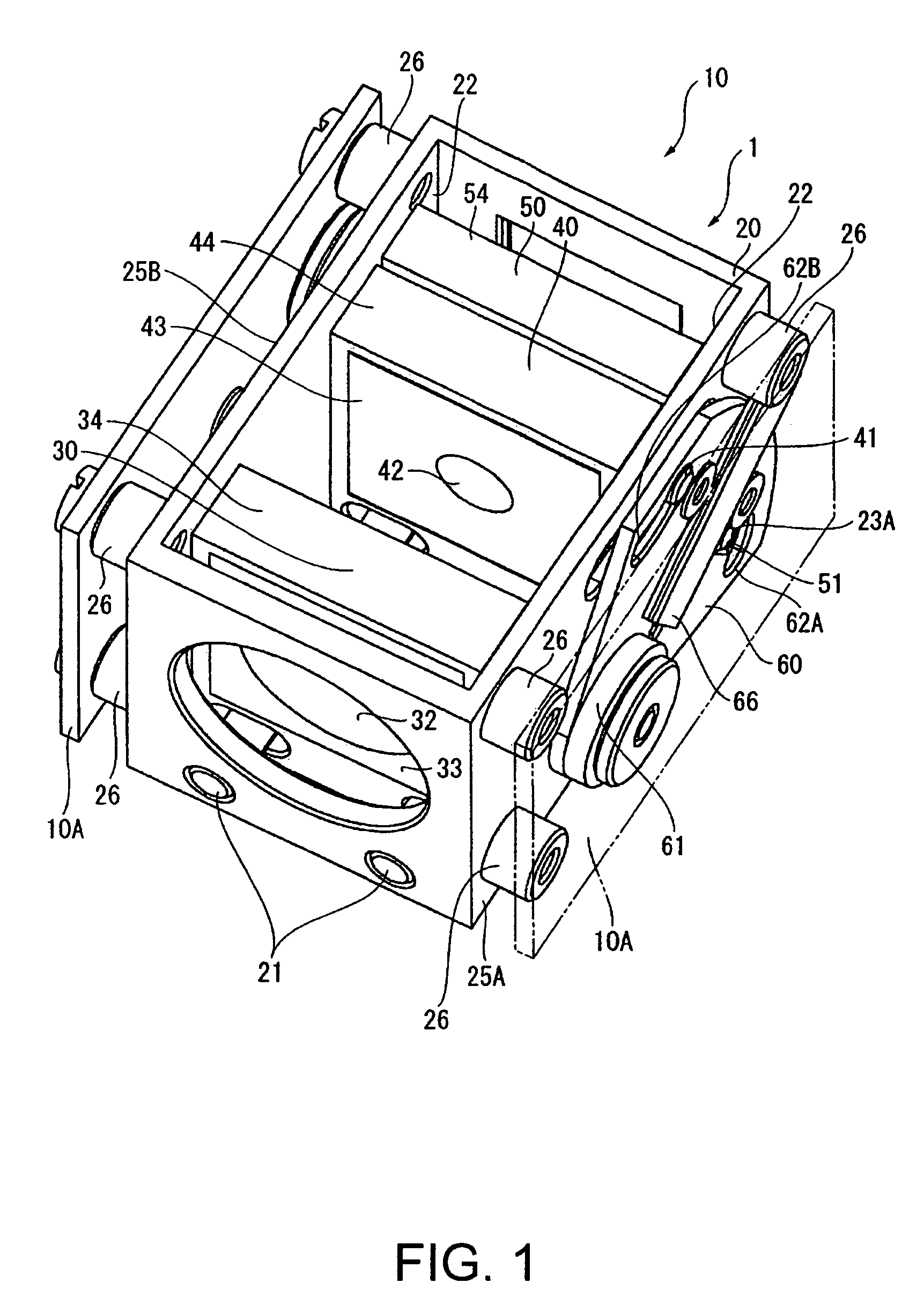
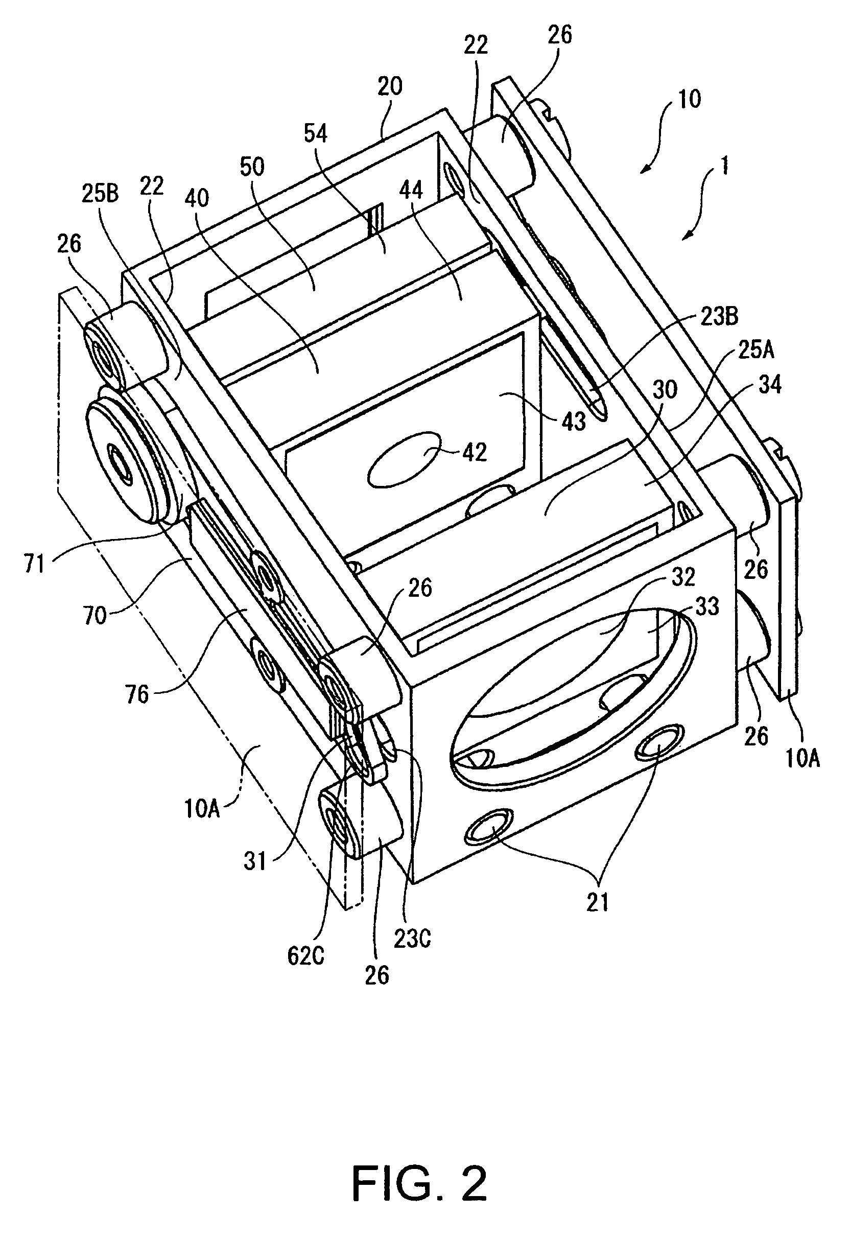
[0075]A lens unit in accordance with a first embodiment of the present invention will now be described. The lens unit 10 is installed in or manufactured as an integral part of a camera that serves as a device.

[0076]In addition to the lens unit 10, the camera is also provided with recording medium for recording an image obtained with lenses 30, 40, 50 that make up the lens unit 10, a drive apparatus (drive unit) 1 configured to drive the lenses 30, 40, 50, and a case that houses all of these components. The camera, recording medium, and case are omitted from the drawings.

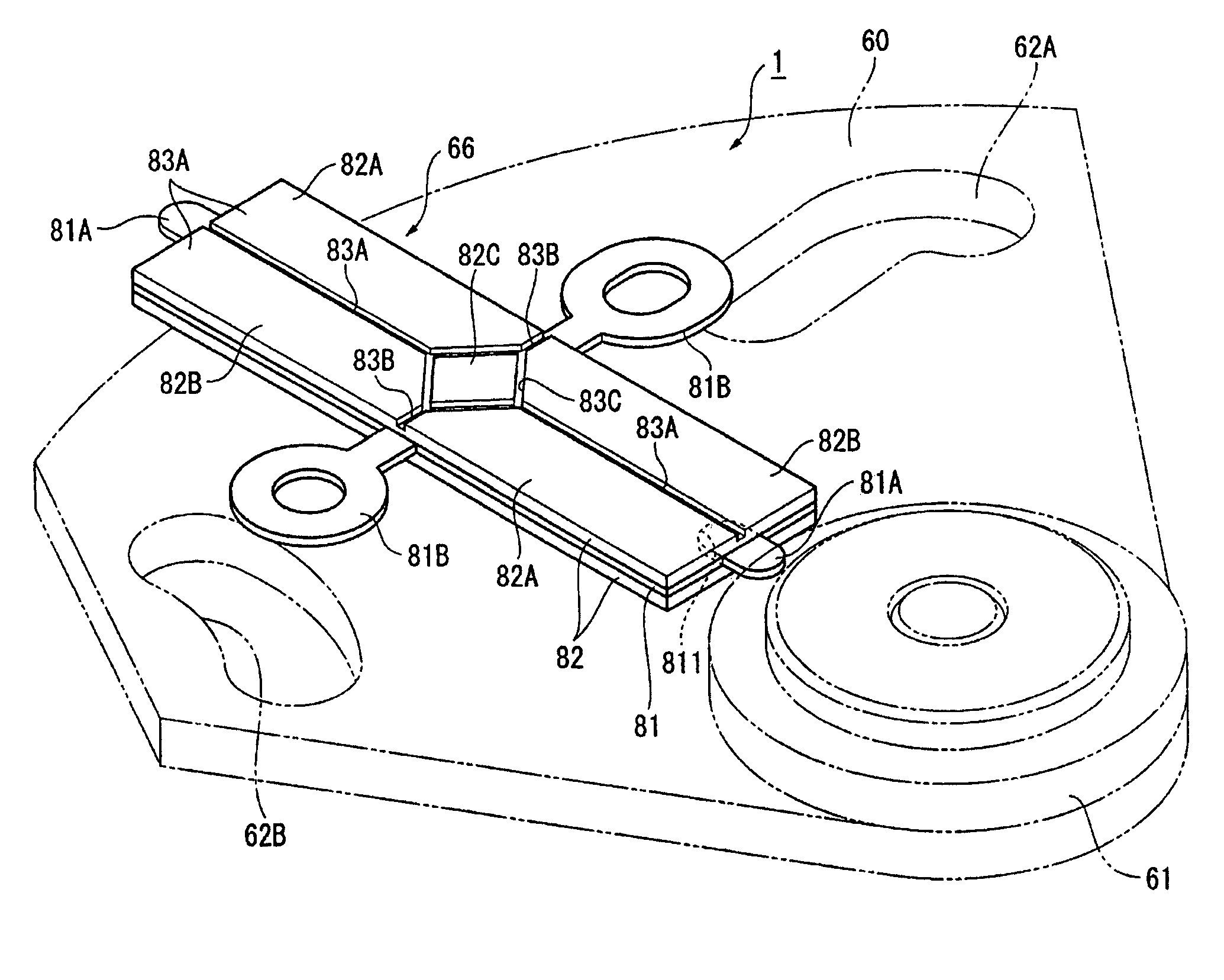
[0077]FIG. 1 is a perspective view of the lens unit 10 viewed from the upper right and FIG. 2 is a perspective view of the lens unit 10 viewed from the upper left FIGS. 3A and 3B illustrate the operation of a cam member 60 and FIGS. 4A and 4B illustrate the operation of a cam member 70. FIG. 5 is an enlarged perspective view of a vibrating body 66 that serves to drive the cam member 60.

[0078]As shown in FIGS. 1 to 5,...

second embodiment

[0148]A second embodiment of the present invention will now be explained. The second embodiment applies a piezoelectric actuator (piezoelectric drive apparatus) in accordance with the present invention to a timepiece. FIG. 9 is a top plan view of a date indicating mechanism 90 included in a time indicating section 200 of a timepiece 9 in accordance with the second embodiment of the present invention. As shown in FIG. 9, the main components of the date indicating mechanism 90 include a piezoelectric actuator 91, a rotor 92 serving as a driven body rotationally driven by the piezoelectric actuator 91, a reduction gear train configured to transfer the rotation of the rotor while reducing the speed thereof and a date indicator wheel 93 arranged and configured to rotate due to the drive force transferred through the reduction gear train The reduction gear train is provided with date indicator driving intermediate wheel 94 and a date indicator driving wheel 95. The piezoelectric actuator ...

working example 1

[0198]The experiment was conducted using the piezoelectric actuator 110A shown in FIG. 19. A plurality of electrodes are electrically insulated from each other by grooves formed in a plating layer on the surface of a piezoelectric element 111A of the piezoelectric actuator 110A and the electrodes are arranged so as to be linearly symmetrical with respect a lengthwise centerline. The piezoelectric element 111A is divided into three approximately equal-sized electrode areas by two lengthwise grooves and the two electrode areas located on both sides are further divided approximately in half by widthwise grooves. Thus, five electrodes are formed on the surface of the piezoelectric element: two diagonally opposite pairs of drive electrodes 112A, 113A and one middle drive electrode 114A A generally rectangular detection electrode 115A is formed inside the drive electrode 114A at the approximate center of the piezoelectric element 111A. The drive electrodes 112A, 113A, 114A and the detecti...


PUM


Abstract

A generally diamond-shaped detection electrode is formed in the approximate center of the piezoelectric element. The strain resulting from the bending secondary vibration mode in the vicinity of the detection electrode is minimized because the detection electrode is formed in such a manner as to include a vibrational node of the longitudinal primary vibrational mode and a vibrational node of the bending secondary vibrational mode. As a result, when the phase difference between the drive signal and the detection signal is detected, the effect of vibration in the bending secondary vibration mode on the detected phase difference can be suppressed and a single drive frequency can be determined with respect to a prescribed phase difference. Thus, the drive performance of the vibrating body with respect to a driven body (i.e., a body driven by the vibrating body) can be reliably improved because, by controlling the drive frequency such that the phase difference equals a prescribed value, the vibrating body can be made to vibrate at a desired frequency and vibrate in such a manner that the desired vibration components are achieved in each vibration mode.

Description

TECHNICAL FIELD[0001]The present invention relates to a piezoelectric actuator configured to drive a driven body by means of the vibration of a piezoelectric element and a device equipped with the piezoelectric actuator.BACKGROUND ART[0002]Some piezoelectric actuators that drive a driven body by means of the vibration of a piezoelectric element are configured to excite a plurality of vibration modes of the piezoelectric element and utilize a combination of these vibration modes to drive the driven body. In order to obtain the desired vibrational path and drive force, such piezoelectric actuators must be designed to maintain the vibration components of each vibration mode in an appropriate manner. As a means of satisfying this requirement, methods have been proposed whereby the drive signal applied to the piezoelectric element is controlled based on a phase difference between the drive signal and a detection signal obtained by detecting the vibrations of the piezoelectric element (se...

Claims


Application Information

Patent Timeline
Patent Type & Authority Patents(United States)
IPC IPC(8): H01L41/04H02N2/00G02B7/04G04C3/12
CPCG04C3/12H01L41/0906H02N2/103H02N2/004H02N2/142H10N30/202
Inventor NAGAHAMA, REIKOYAMAZAKI, YUTAKA
Owner SEIKO EPSON CORP
Why Eureka
Try Eureka