RF plasma source with quasi-closed ferrite core

a plasma source and quasi-closed technology, applied in the field of radio frequency plasma sources, can solve problems such as penetration of alternating magnetic fluxes, and achieve the effects of improving the decompression of plasma electrons, reducing the value of magnetic field b, and high electron energy

Inactive Publication Date: 2009-04-07
AMPRES INC
View PDF2 Cites 4 Cited by
  • Summary
  • Abstract
  • Description
  • Claims
  • Application Information

AI Technical Summary

Benefits of technology

[0008]Each bone-shaped port provided in the discharge chamber walls (3 in FIGS. 2, 4) is shaped of two through side openings (4 in FIGS. 2, 4), corresponding to the disconnected ends of the quasi-closed ferrite core, and a through slot (5 in FIGS. 2, 4) connecting these openings. The alternating magnetic field B passing throughout the ferrite core gaps (operating gaps) within the discharge chamber induces in the operating gaps a vortex electric field E capable of accelerating the electrons, and consequently to excite and to maintain discharge plasma in an operating gas filling this chamber (see FIGS. 2, 3, 5, 6, 7). The actual electron current induced in the plasma by the vertex electrical field E forms closed loops of alternating current (virtual secondary winding) decreasing the value of the magnetic field B (having a minimum at a gap center plane in any regard) within gaps that improves the decompression of plasma electrons from the walls and provides in this way plasma wall insulation.SUMMARY OF INVENTION
[0009]The present invention provides a well localized high purity plasma source comprising a quasi-closed ferrite core (1 in FIG. 2) disposed in coils (2 in FIG. 2) of a primary winding, a discharge chamber (3 in FIG. 2) equipped with opposed bone-shaped ports of a vacuum sealed high temperature insulator (quartz, silica, ceramic), and inserted in operating gaps of the quasi-closed ferrite to fit side-openings (4 in FIG. 2) of the bone-shaped ports with disconnected ends of the quasi-closed ferrite core. A vacuum sealed through slot (5 in FIG. 2) connecting the side openings (4 in FIG. 2) serves to prevent formation of short circuits around the side openings (4 in FIG. 2) admitting the alternating magnetic field B of the quasi-closed ferrite core into the discharge chamber. A flux of the alternating magnetic field B passing throughout the discharge chamber induces the alternating vertex electrical field E acting along loops enveloping the magnetic flux as is shown in FIG. 3, wherein the discharge chamber with its bone-shaped ports is not shown for clarity. The electrons accelerated in the electrical field E, igniting and maintaining discharge plasma in the operating gaps of the quasi-closed ferrite core, develop the actual alternating vertex electron currents forming a virtual secondary winding in the plasma. These alternating vertex currents decrease the value of the magnetic field B in the operating gaps and improve in this manner insured plasma wall thermoinsulation. The effect of the thermoinsulation is emphasized by a natural decrease of the electromagnetic energy density, and consequently electromagnetic field pressure toward the central plane of the gaps. Relatively high electron energy (20-50 eV) developed in the vertex electrical fields promotes plasma expansion by ambipolar diffusion in the preferred direction defined by an open space. In FIG. 3, the possible directions of plasma propagation along the main plane of the quasi-closed core symmetry are shown by fashioned arrows.
[0010]The small side openings of the bone-shaped ports do not face intense plasma because the voltage acquired by the electrons along loops less than the aperture of the openings (4 in FIGS. 2, 4) in this area is significantly less than the voltage acquired along wider loops surrounding a bulk part of the magnetic flux anywhere in the chamber, according to Faraday's Law. The through slot (5 in FIGS. 2, 4) connecting the side openings of the bone-shaped port is cut to prevent formation of a short circuit around the openings admitting the alternating magnetic field B into the chamber. To protect the insulator closing this slot from a direct interaction with dense plasma, this slot cross-section can be provided with a chevron or V shape. The insulator closing and vacuum-sealing the side openings and engaged with the slot of the bone-shaped port can be, for example, designed as a single rectangular solid plate (6 in FIG. 4) sealed by the O-ring (8 in FIG. 4) from the atmosphere side of the discharge chamber as is shown in FIG. 4. The sizes of the side openings c1 and d1 (see FIG. 4) of the bone-shaped port should be insignificantly more than the corresponding sizes c and d (see FIG. 3) of the quasi-closed core 1 aperture to permit a bulk portion of the magnetic flux provided at this location to pass. The preferred width g of the slot 5 (see FIG. 4) should not be decreased to a value less than 1-2 mm due to the fact that a further decrease can create a significant electric capacity between the closest opposite sides of the slot. This forms in this manner a capacitively shorted circuit for induced virtual alternating vertex currents, hampering in this case a penetration of the alternating magnetic flux into the chamber. The preferred cross section of the slot is chevron-shaped to prevent a direct plasma interaction with the portion of the insulator 6 (in FIG. 4) facing the plasma.

Problems solved by technology

This forms in this manner a capacitively shorted circuit for induced virtual alternating vertex currents, hampering in this case a penetration of the alternating magnetic flux into the chamber.

Method used


Image

  • RF plasma source with quasi-closed ferrite core
  • RF plasma source with quasi-closed ferrite core
  • RF plasma source with quasi-closed ferrite core

Examples


Embodiment Construction

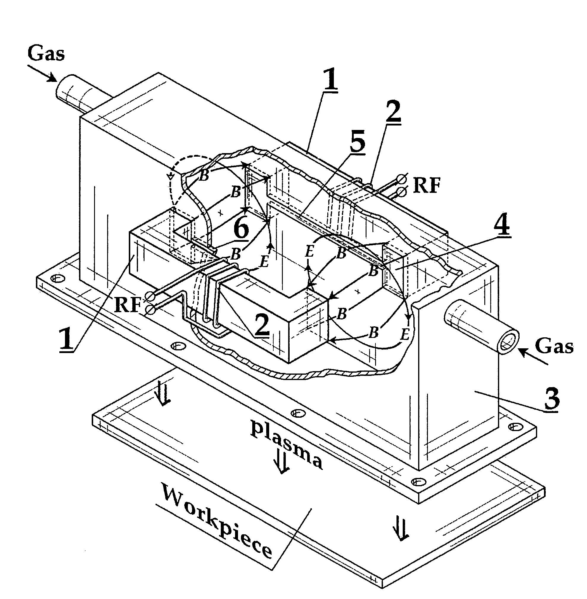
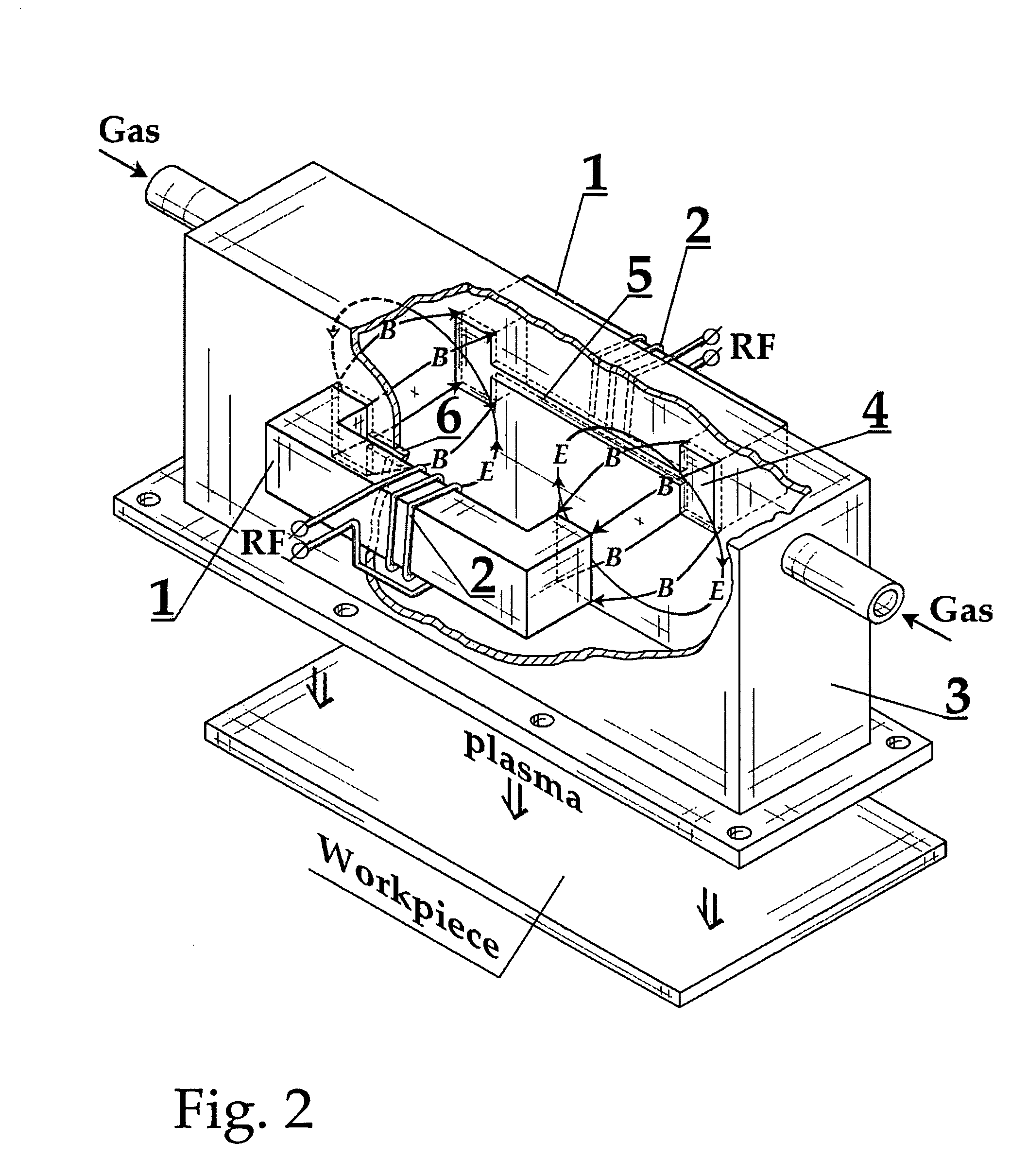
[0021]The plasma source with a quasi-closed ferrite core made according to one embodiment of the present invention is shown in FIG. 2 by way of a three dimensional partial sectional view of the device. The device comprises a quasi-closed O-type ferrite core 1 of two symmetrically placed and disconnected or spaced U-shaped halves disposed in two coils 2 forming a primary winding connected to an RF generator, and a metallic (aluminum, copper) open sided box-type housing having a discharge chamber with two opposite closest walls equipped with opposed symmetrical bone-shaped ports comprised each of two trough side-openings 4 corresponding in dimension to the disconnected or spaced ends of quasi-closed ferrite core 1, and a through slot 5 connecting these openings. The bone-shaped ports are closed and vacuum-sealed by a high-temperature insulator 6 (quartz, ceramic, sapphire). The housing 3 is provided with two operating gaps formed between the disconnected ends of the quasi-closed ferri...


PUM


Abstract

An inductively coupling plasma source having a primary winding powered directly from a radio frequency source and a quasi-closed O-type ferrite core comprised of two equal U-shaped core halves separated from one another to form two operating gaps between aligned spaced ends of the core halves with the quasi-closed ferrite core disposed in the primary winding. A metallic housing is provided having a discharge chamber therein and two opposed walls with symmetrically opposed bone-shaped ports, wherein the ports are closed and vacuum sealed with insulating material and each is provided with two side openings dimensionally respectively fitted to and engaged with the spaced ends of the quasi-closed ferrite core, and a through slot connecting the side openings along their centerline for inductive excitation and maintenance of plasma in the operating gaps positioned within the discharged chamber.

Description

FIELD OF INVENTION[0001]The present invention relates to RF (radio frequency) plasma sources applicable to plasma processing technologies. More specifically, the present invention relates to plasma sources utilizing an O-type closed ferrite core cut across to provide two equal U-shaped disconnected halves to form two operating gaps (hereinafter referred a quasi-closed ferrite core). The quasi-closed ferrite core is mounted at room atmosphere within a discharge chamber of a metallic housing disposed in the operating gaps. The discharge chamber is equipped with special small vacuum-sealed ports of an insulator capable to permit a core induced alternating magnetic flux to pass in this manner throughout the chamber. The quasi-closed ferrite core has an actual primary winding supplied by RF power of 0.1-1 MHz, and a virtual secondary closed winding is formed by the electrons of gas-discharge plasma in the discharge chamber filled with a gas of a controllable pressure. The range of operat...

Claims


Application Information

Patent Timeline
Patent Type & Authority Patents(United States)
IPC IPC(8): H01J7/24
CPCH01J37/321
Inventor SHUN'KO, EVGENY V.
Owner AMPRES INC
Why Eureka
Try Eureka