Detachable lens apparatus, camera system and camera for accurate automatic focusing using two driving mechanisms

a technology of automatic focusing and lens apparatus, which is applied in the field of lenses, camera systems and cameras, can solve the problems of limited driving accuracy of the focusing system lenses and the difficulty of accurately stopping the focusing lens at the in-focus position, and achieve the effect of high accuracy within a short tim

Inactive Publication Date: 2009-04-07
CANON KK
View PDF7 Cites 5 Cited by
  • Summary
  • Abstract
  • Description
  • Claims
  • Application Information

AI Technical Summary

Benefits of technology

[0014]It is an object of the present invention to provide a lens driving apparatus which can move a focusing lens to an in-focus position highly accurately within a short time by an AF system, and an optical apparatus having the same.
[0015]Particularly, it is an-object of the present invention to provide a lens driving apparatus which uses first driving means for rough adjustment and second driving means for fine adjustment as a drive source for driving a focusing lens in the direction of the optical axis thereof, and in which the first driving means and the second driving means can be driven independently of each other to thereby effect high-speed and moreover highly accurate drive control, and an optical apparatus having the same.

Problems solved by technology

In the conventional AF apparatus as described above, however, rough adjustment must be manually effected and there is a limitation in the driving accuracy of the focusing system lenses, and there has been the problem that hunting occurs.
When as a method of solving this, for example, a high-speed type actuator is used to shorten the focusing time, it is possible to shorten the time for which the focusing lens is driven to the vicinity of the in-focus position, but there has been the tendency that the control during minute driving from the vicinity of the final in-focus position to the in-focus position is not in time and it becomes difficult to accurately stop the focusing lens at the in-focus position.

Method used


Image

  • Detachable lens apparatus, camera system and camera for accurate automatic focusing using two driving mechanisms
  • Detachable lens apparatus, camera system and camera for accurate automatic focusing using two driving mechanisms
  • Detachable lens apparatus, camera system and camera for accurate automatic focusing using two driving mechanisms

Examples


first embodiment

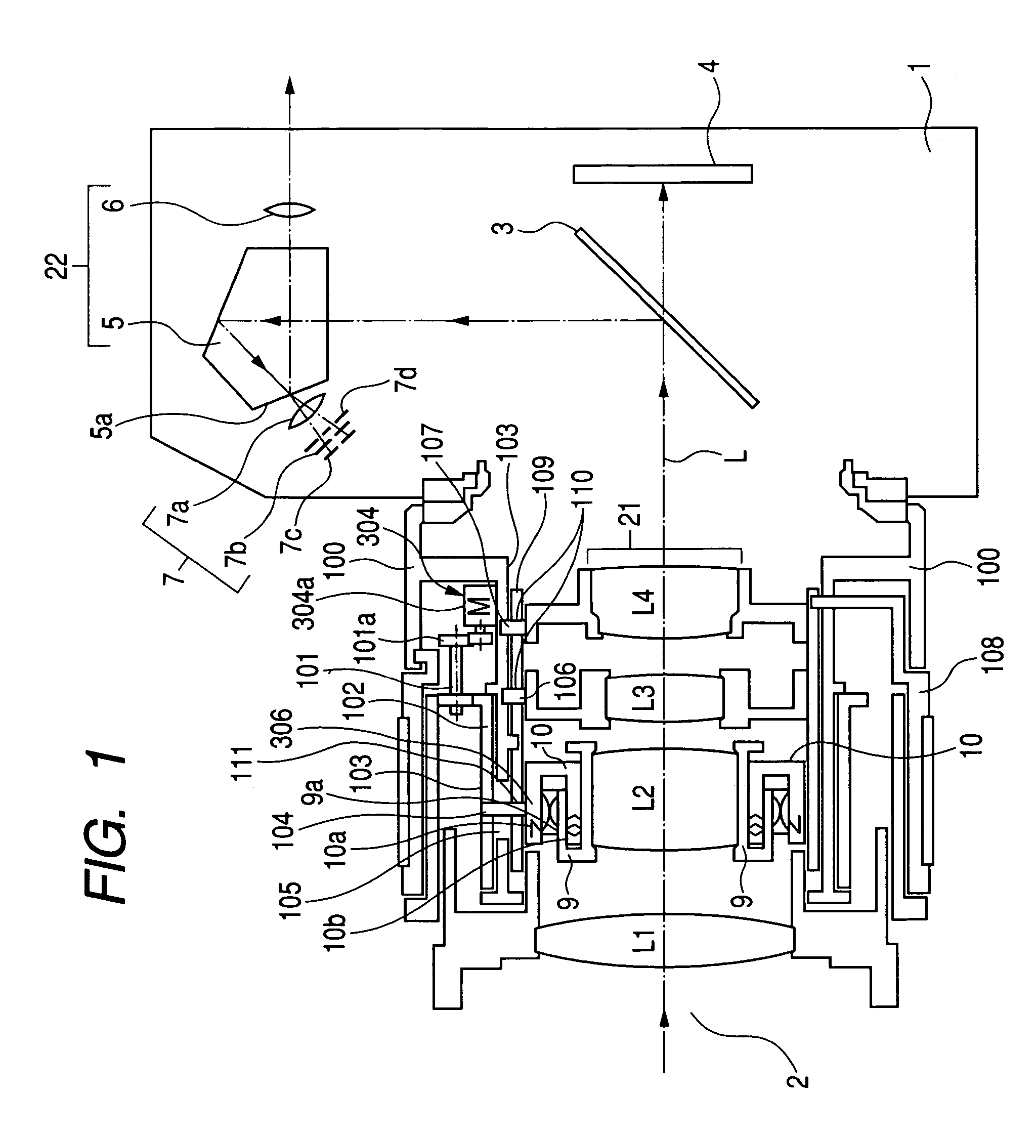
[0028]FIG. 1 is a cross-sectional view of the essential portions of a first embodiment when the lens apparatus of the present invention is applied to a digital single-lens reflex camera (camera system) of a lens interchangable type.

[0029]In FIG. 1, the reference numeral 1 designates a camera main body, and the reference numeral 2 denotes an interchangeable lens mounted on the camera main body 1. The camera main body 1 and the interchangeable lens 2 comprise constituent portions shown below.

[0030]The reference numeral 21 designates a photo-taking optical system having first, second, third and fourth lens units L1, L2, L3 and L4. The reference numeral 3 denotes a half-transmitting half-mirror (main mirror) disposed on the optical axis L of the photo-taking optical system 21, and this half-mirror 3 transmits therethrough part of beam based on an object image passed through the photo-taking optical system 21 and directs it to an image pickup element 4, and reflects part of the beam and ...

second embodiment

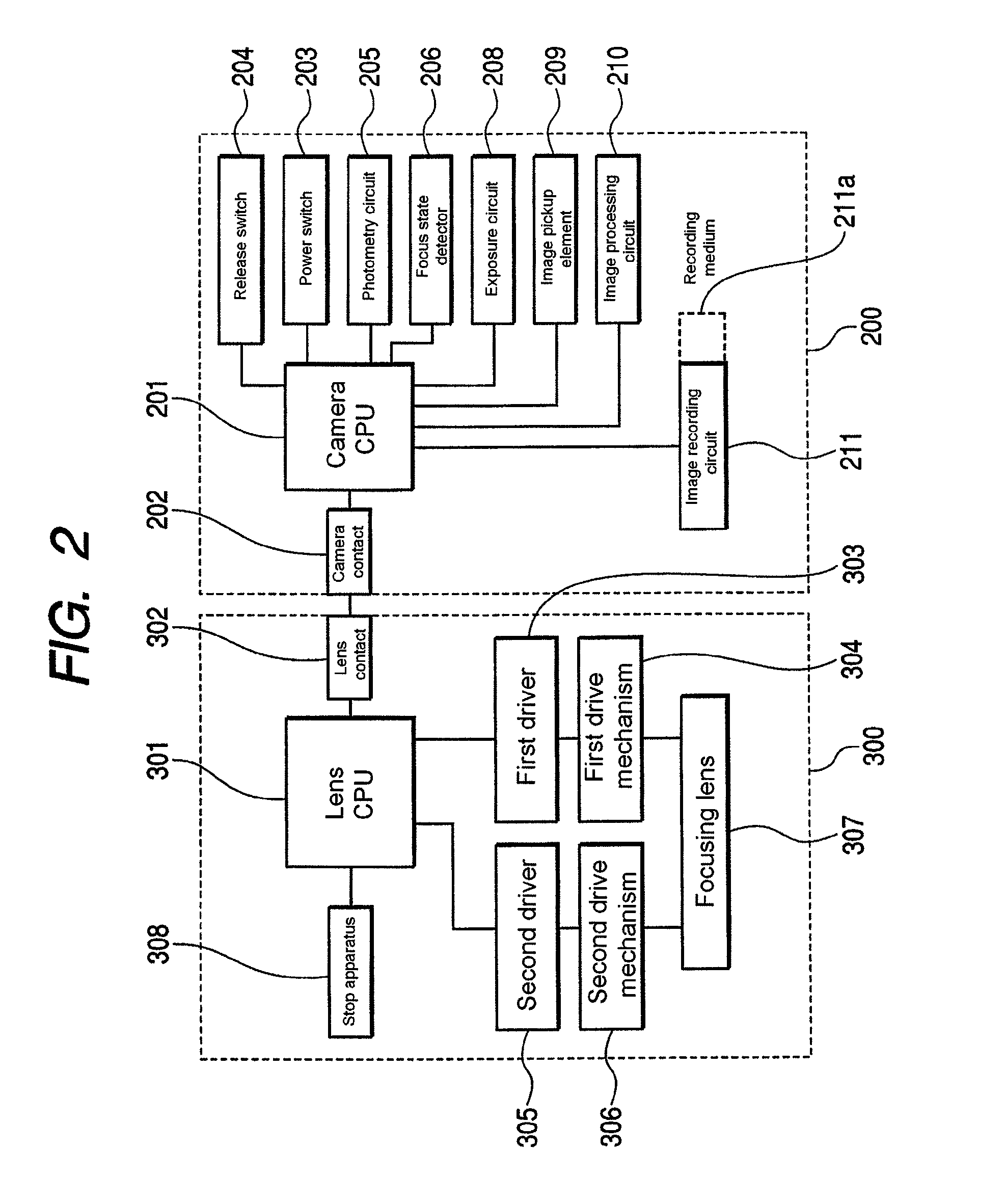
[0073]FIG. 4 is a block diagram of a digital single-lens reflex camera (camera system) of a lens interchangeable type according to a second embodiment of the present invention. In FIG. 4, the same elements as the elements shown in FIG. 2 are given the same reference characters.

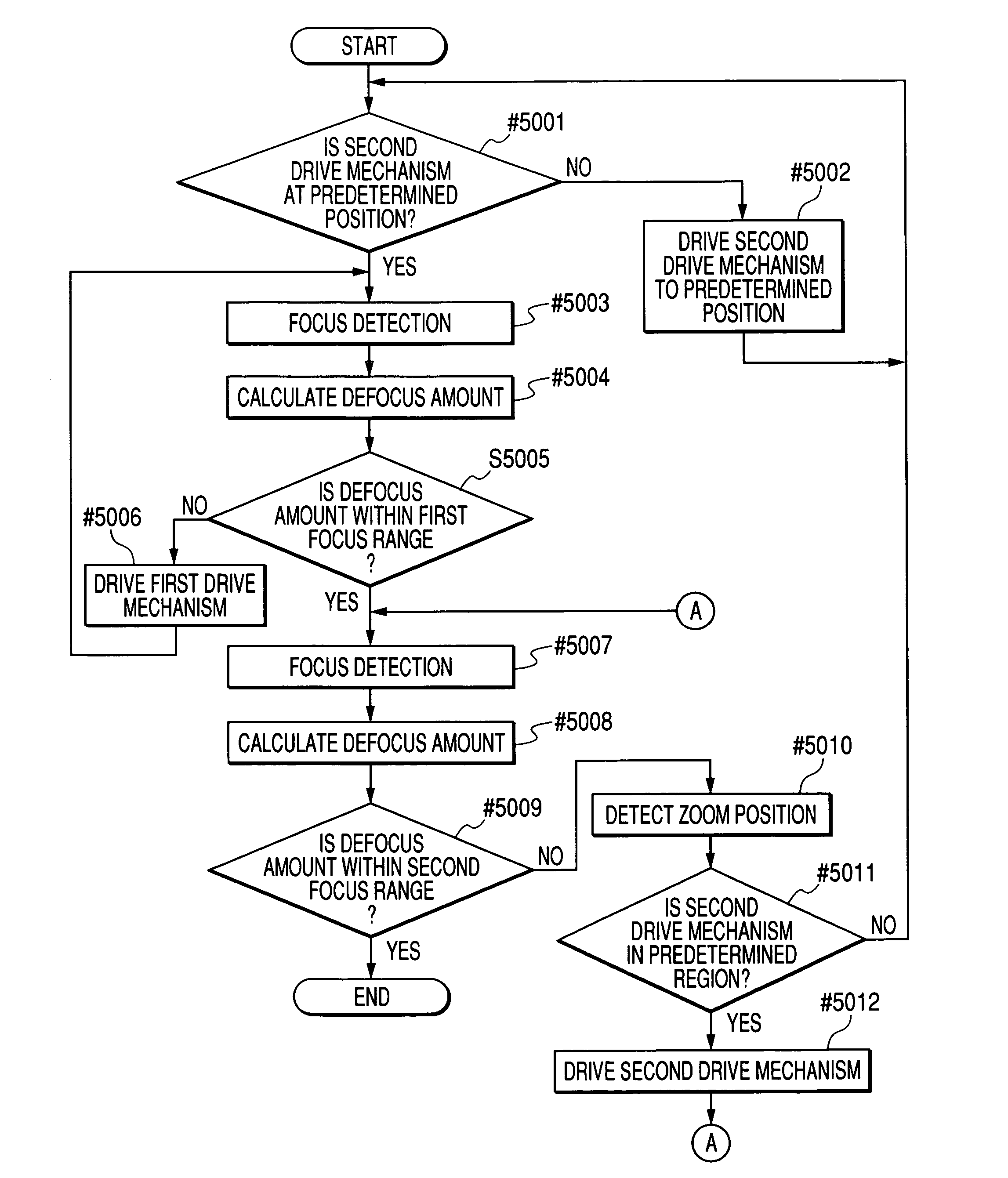
[0074]The difference of the present embodiment from the aforedescribed first embodiment resides in a construction having, as the focus state detector, two focus detecting units, i.e., a first focus state detector 206 using the phase difference process, and a second focus state detecting unit using a contrast process using the image pickup element 209 and the focus detection processing circuit 207. In the other points, the construction and optical action of the present embodiment are substantially similar to those of the first embodiment, whereby a similar effect is obtained.

[0075]That is, in the present embodiment, in the above-described construction, focus detection is effected by the first focus state, detec...


PUM


Abstract

Provided are a lens apparatus and an optical apparatus having the same, the lens apparatus including a lens holding member holding a lens, a supporting member for supporting the lens holding member movably in the direction of the optical axis of the lens, a first drive mechanism for moving the supporting member in the direction of the optical axis, and a second drive mechanism for moving the lens holding member in the direction of the optical axis, wherein a focusing lens can be moved to an in-focus position within a short time and highly accurately by an AF system.

Description

BACKGROUND OF THE INVENTION[0001]1. Field of the Invention[0002]This invention relates to a lens apparatus, a camera system and a camera, and particularly is suitable for an optical apparatus such as, for example, a video camera or a still camera using two drive mechanisms, i.e., a first drive mechanism and a second drive mechanism, as a drive source for driving a focusing lens in the direction of the optical axis thereof, and designed such that the two drive mechanisms are driven independently of each other, whereby high-speed and highly accurate drive control can be effected.[0003]2. Related Background Art[0004]There have heretofore been proposed numerous optical apparatuses (camera systems) carrying thereon an automatic focus adjusting (hereinafter referred to also as “AF”) apparatus for detecting the focus adjusted state of a photo-taking lens or the distance to an object, and driving an actuator (drive source) such as a motor on the basis of the result of the detection to there...

Claims


Application Information

Patent Timeline
Patent Type & Authority Patents(United States)
IPC IPC(8): H04N5/232G03B13/00G02B7/08G02B7/04H04N5/225
CPCH04N5/23209H04N5/23212H04N23/663H04N23/672H04N23/673
Inventor KAWAI, TOHRUISHIKAWA, MASANORIKASHIWABA, SEIICHISHINOHARA, MITSURUSATO, SHIGEKINAGAO, YUKI
Owner CANON KK
Why Eureka
Try Eureka