Method for operating a motorized screen

a motorized screen and screen technology, applied in the direction of curtain suspension devices, projectors, building components, etc., can solve the problems of installation difficulty, toggling of latching means, etc., and achieve the effect of improving operation methods, reducing drawbacks, and facilitating the procedure for configuring and adjusting the motorized screen devi

Inactive Publication Date: 2009-04-07
SOMFY SAS
View PDF6 Cites 9 Cited by
  • Summary
  • Abstract
  • Description
  • Claims
  • Application Information

AI Technical Summary

Benefits of technology

[0019]The aim of the invention is to provide a method for operating a motorized screen device making it possible to alleviate the drawbacks cited and making it possible to improve the methods of operation known from the prior art. In particular, the invention proposes a method of operation making it possible to make easier the procedures for configuring and adjusting the motorized screen device and to reduce the time required to complete them. The invention proposes in particular to make easier the procedures for defining the positions of the means of latching of the device.

Problems solved by technology

The passage of the load bar of the device to a height level with these latching means causes the toggling of the latching means.
This characteristic is a problem for the implementation of the method described previously.
Specifically, on account of these small distances, it is very difficult for the installer, during the installation of the device, to bring the windable element directly into a position lying between the second and the fourth position.

Method used


Image

  • Method for operating a motorized screen
  • Method for operating a motorized screen
  • Method for operating a motorized screen

Examples


Embodiment Construction

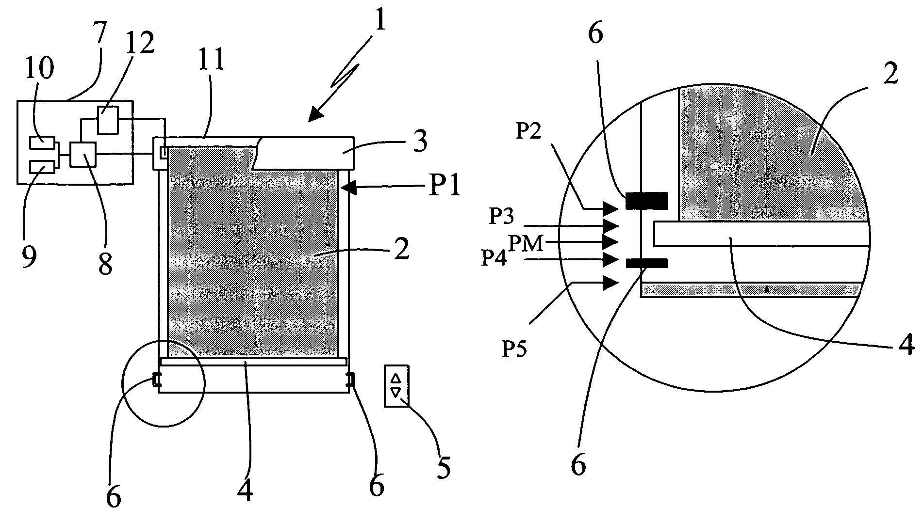
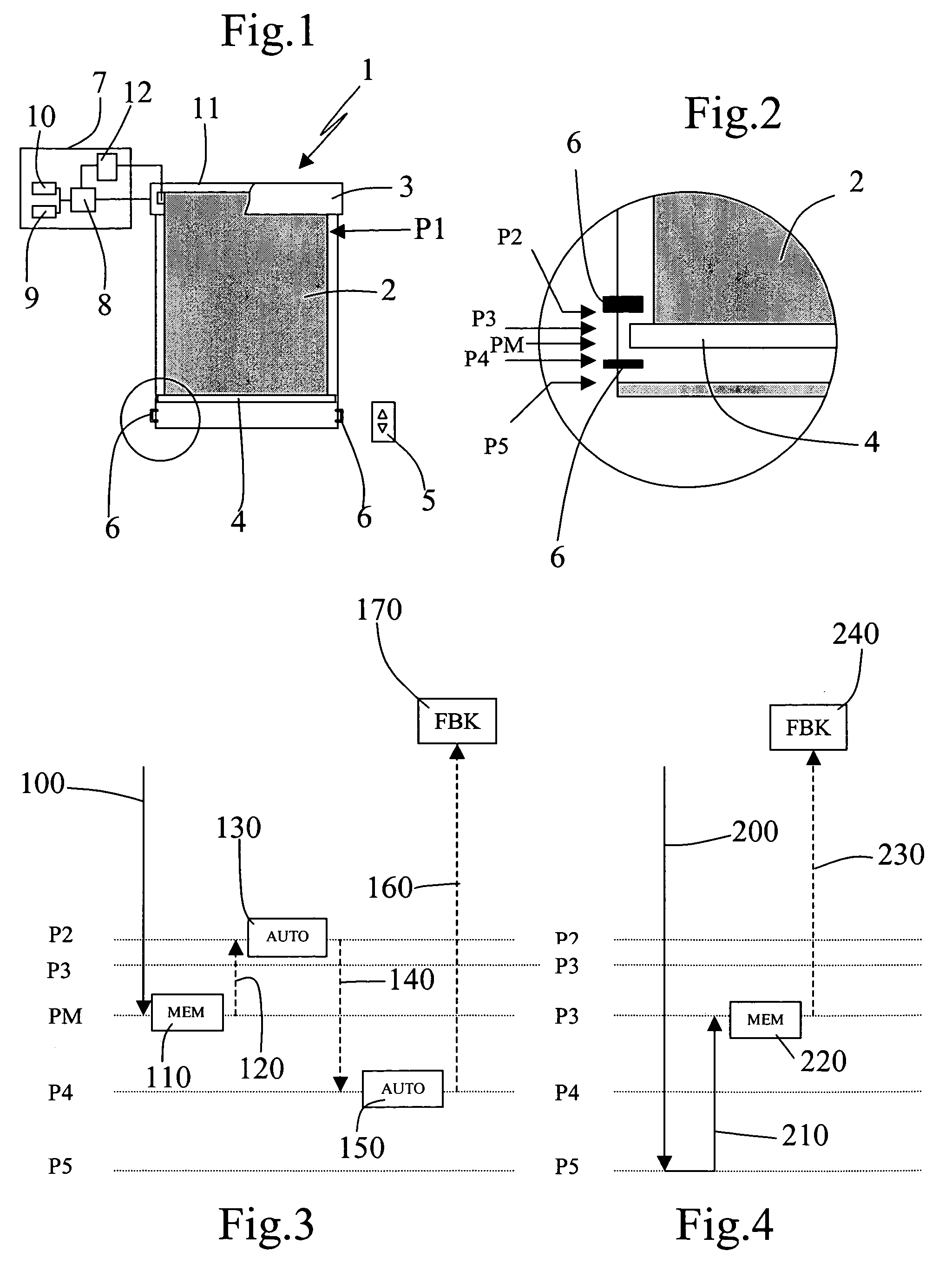
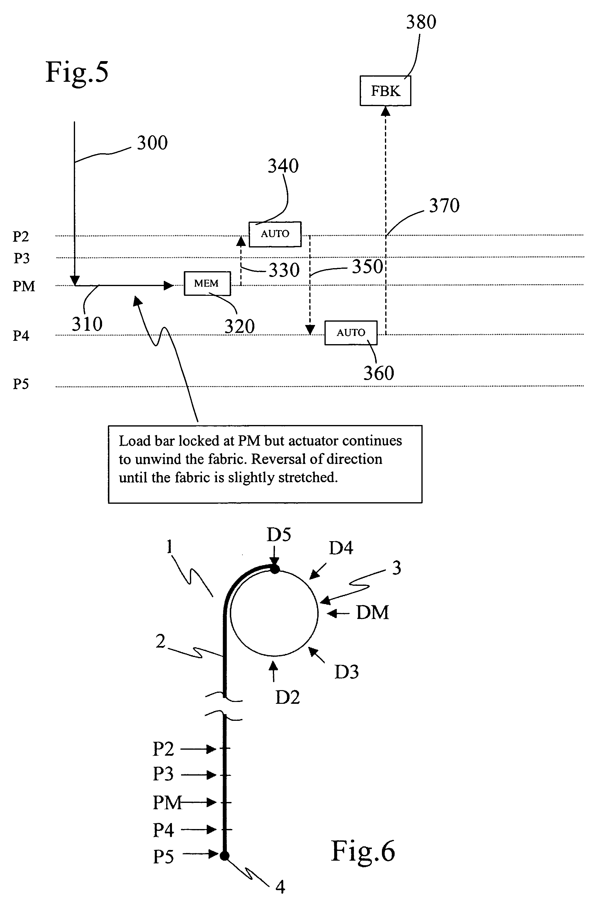
[0031]A motorized screen device 1 is represented in FIG. 1. This device comprises a windable element 2 linked at one of its ends to a winding tube 3 and at the other of its ends, called the free end, to a load bar 4 whose ends are guided by guiding rails disposed in a building on either side of an opening that the windable element is intended to cover.

[0032]The displacements of the windable element 2 or screen are controlled by the rotational displacements of the winding tube 3. A tubular gear motor disposed inside the winding tube 3 allows the latter to be driven. The movements of the gear motor are controlled by a control unit 7 linked to the gear motor, to sensors 10, 12 and to a user interface 5 with which a user can control the movements of the windable element. The device comprises a sensor 12 of the angular position of the winding tube 3 and can also comprise a torque sensor 10 for sensing the torque exerted by the gear motor so as to detect obstacles and / or the ends of trave...


PUM


Abstract

The method applies to a motorized screen device comprising a screen windable on a winding tube, and at least one means for latching the free end of the screen defining a position termed latched in the direction of winding, the latching being activated in this direction if the free end of the screen previously reaches at least one position of reversal, to which corresponds for the unwinding a value of angular position of the winding tube termed the position of reversal of rotation, situated beyond the latched position in the direction of unwinding of the screen. According to the method, in a mode of configuration of the latching of the screen, the installer proceeds merely to record the value of a chosen angular position, termed the recorded rotation reversal position, this position being situated at the level of or beyond the position of reversal of rotation, in the direction of unwinding of the screen.

Description

[0001]This application claims priority benefits from French Patent Application No. 04 11349 filed Oct. 25, 2004.BACKGROUND OF THE INVENTION[0002]The invention relates to a method for operating a motorized screen device comprising a screen windable on a winding tube whose angular position is measured by a sensor, and at least one means of latching of the free end of the screen defining a position termed latched position in the direction of winding, the latching being activated in this direction if the free end of the screen previously reaches at least one position of reversal, to which corresponds for the unwinding a value of angular position of the winding tube termed the position of reversal of rotation, situated beyond the latched position in the direction of unwinding of the screen. The invention also relates to a motorized screen device for the implementation of such a method.DESCRIPTION OF THE PRIOR ART[0003]Known screen devices comprise a windable element fixed on the one hand...

Claims


Application Information

Patent Timeline
Patent Type & Authority Patents(United States)
IPC IPC(8): G03B21/56A47G5/02
CPCE06B9/80E06B9/86G05B19/42
Inventor CANON, SYLVAINNOIR, CELINECATHALA, JEAN-PIERREGUILLEMOT, ERIC
Owner SOMFY SAS
Why Eureka
Try Eureka