Steam channeling structure

a technology of steam iron and channeling structure, which is applied in the direction of vacuum cleaners, carpet cleaners, textiles and paper, etc., can solve the problems of not being able to carry or move, not being able to achieve the effect of convenient carrying and storage, and not being able to achieve convenient transportation and storag

Inactive Publication Date: 2009-04-14
TSEN SAMSON
View PDF23 Cites 47 Cited by
  • Summary
  • Abstract
  • Description
  • Claims
  • Application Information

AI Technical Summary

Benefits of technology

[0007]The steam channeling structure thus formed allows one steam iron to perform steam ironing and steam cleaning functions at the same time. When in use to do steam cleaning, different cleaning tools may be selected according to cleaning requirements to be coupled with the coupling dock. Thus utilization of the steam iro

Problems solved by technology

It is not desirable in terms of convenience or economy.
As a result, the clothes being treated are easily damped.
Total size is bulky and not easy to

Method used


Image

  • Steam channeling structure
  • Steam channeling structure
  • Steam channeling structure

Examples


Embodiment Construction

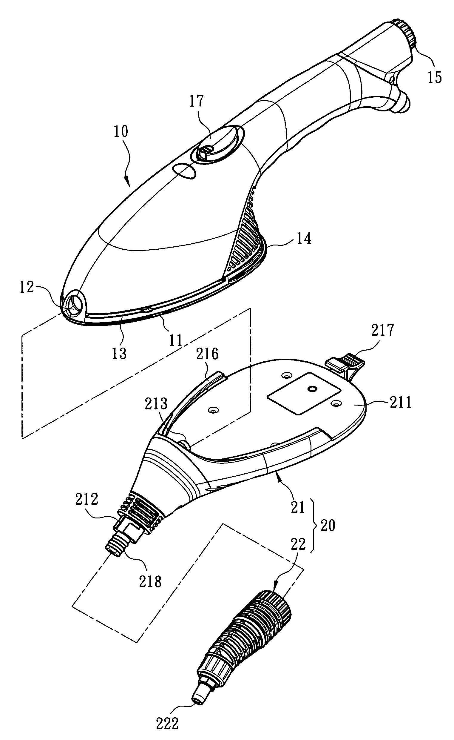
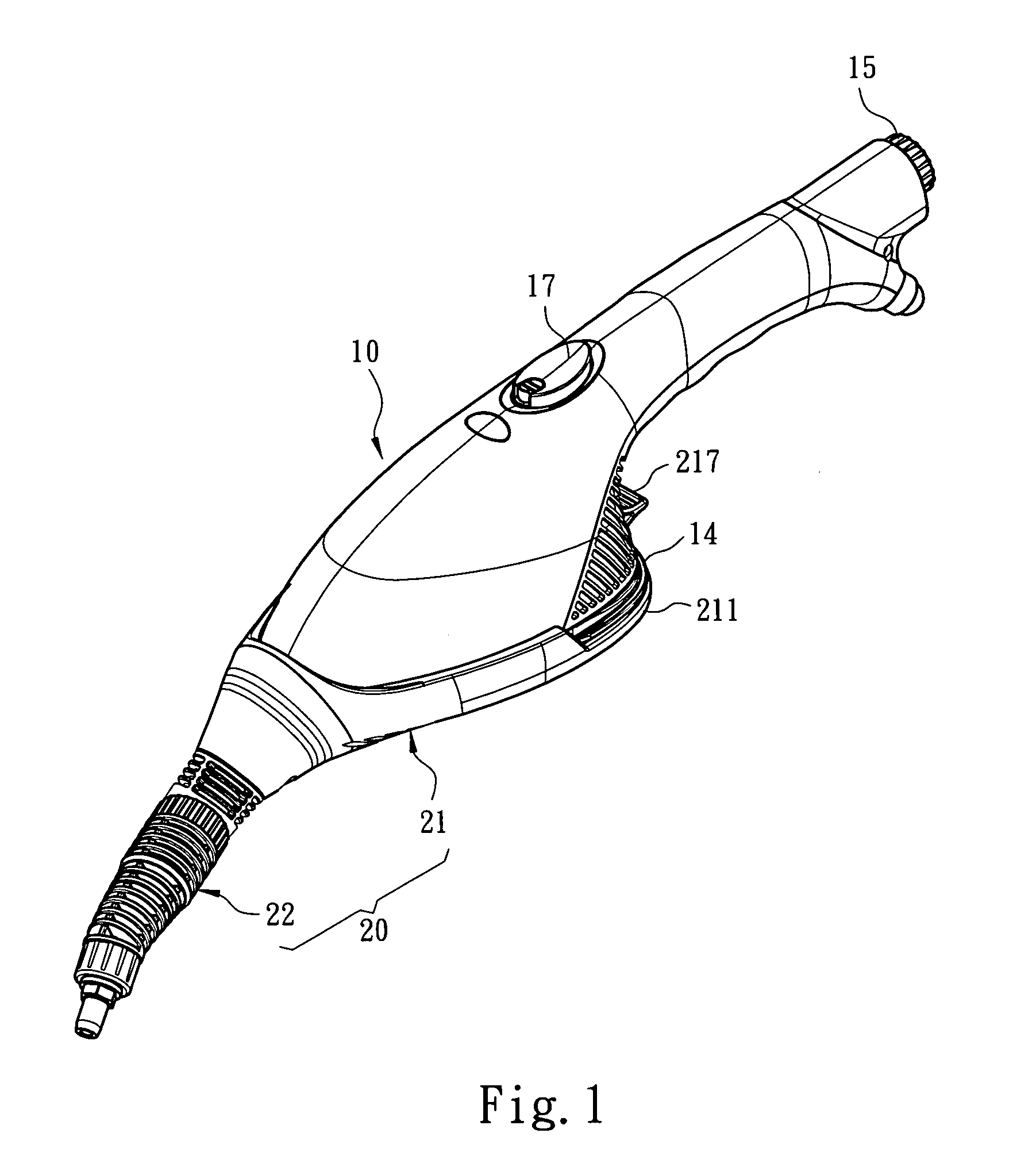
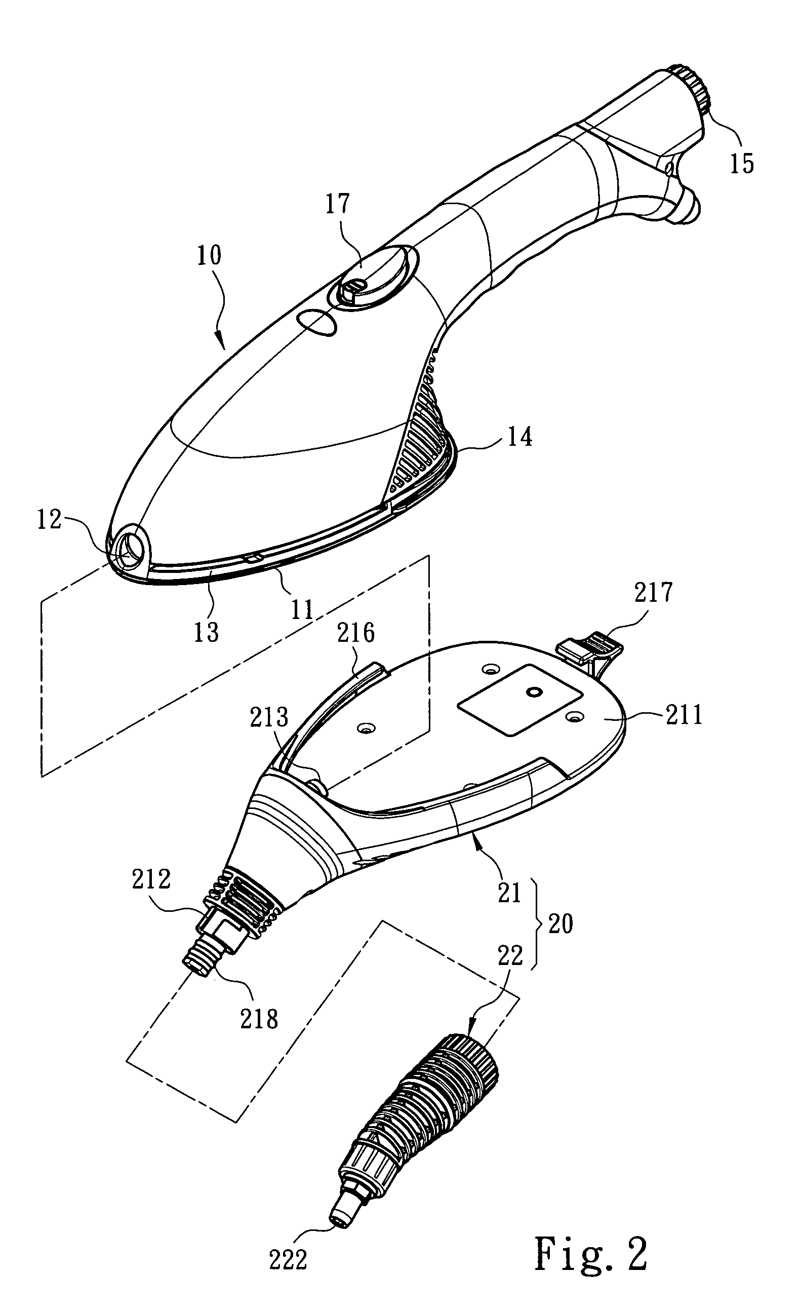
[0017]Please refer to FIGS. 1, 2 and 3 for an embodiment of the invention incorporating with a steam iron. The steam channeling structure 20 of the invention is adopted for use on a steam iron 10 to transform the steam iron to provide steam cleaning function. The steam iron 10 includes a soleplate 11 to be heated to perform ironing function and at least one steam vent 12. The steam channeling structure 20 includes a coupling dock 21 and a cleaning tool 22 fastened to the coupling dock 21. The coupling dock 21 is mounted onto the steam iron 10, and has a protective portion 211 covering the soleplate 11 and a steam directing portion 212 communicating with the steam vent 12 to direct steam discharged from the steam vent 12. The protective portion 211 aims to isolate the soleplate 11 from in contact with users to avoid scalding the users resulting from incidental touching. To enhance heat isolation effect of the protective portion 211, it has a heat isolation layer located thereon. The ...


PUM


Abstract

A steam channeling structure adopted for use on a steam iron to transfer steam to perform cleaning function. The steam iron includes at least a soleplate heated to perform ironing function and at least one steam vent. The steam channeling structure includes a coupling dock and at least one cleaning tool mounted onto the coupling dock. The coupling dock has a protective portion to cover the soleplate and a steam directing portion communicating with the steam vent to direct steam discharged through the steam vent. The cleaning tool has a steam passage connecting to the steam directing portion and a steam channeling vent located in the steam passage. Steam generated by the steam iron is conveyed through the steam directing portion to the steam channeling vent to be discharged to perform steam cleaning function on a selected article.

Description

FIELD OF THE INVENTION[0001]The present invention relates to a steam channeling structure and particularly to a steam channeling structure to transform a steam iron to provide steam cleaning function.BACKGROUND OF THE INVENTION[0002]Steam iron aims to remove wrinkles of clothes or fabrics through heat. It is widely used in houses and businesses. The steam iron ejects steam during ironing the clothes. Compared with the traditional iron there is no need to spray moisture. Moreover, the ejected steam can protect the clothes from being damaged by the high temperature of the iron. In addition, the steam can quickly penetrate inside the fibers of the clothes and heat evenly so that the fibers can be rearranged to form a desired shape. References of steam iron can be found in U.S. Pat. Nos. 6,935,056, 6,438,876, 6,079,133, 5,642,579 and publication No. 20070102414. They mostly have an iron body with a steam chamber inside to generate steam which is delivered to at least one steam output ve...

Claims


Application Information

Patent Timeline
IPC IPC(8): D06F75/20D06F75/06
CPCA47L13/22A47L13/225D06F75/10D06F75/20D06F79/00
Inventor TSEN, SAMSON
Owner TSEN SAMSON
Why Eureka
Try Eureka