Device for locking an electric apparatus onto a supporting rail

a technology for attaching devices and electric appliances, which is applied in the direction of washstands, lighting support devices, and coupling device connections, etc., can solve the problems of awkward use, unpractical attaching of modules, and the movement of hooks, and achieves good coupling of electric devices and simple design. , the effect of simple design

Active Publication Date: 2009-04-14
SCHNEIDER ELECTRIC IND SAS
View PDF12 Cites 25 Cited by
  • Summary
  • Abstract
  • Description
  • Claims
  • Application Information

AI Technical Summary

Benefits of technology

[0009]The object of the invention is to propose a device for locking an electric apparatus onto a supportin...

Problems solved by technology

In this patent, the attachment of the module is not very practical because it requires two successive manipulations.
Screwing/unscrewing the screw causes the plate to move which in turn causes the hooks to move.
In addition, with such a configuration, a user must carry out an action on the scr...

Method used


Image

  • Device for locking an electric apparatus onto a supporting rail
  • Device for locking an electric apparatus onto a supporting rail
  • Device for locking an electric apparatus onto a supporting rail

Examples


Embodiment Construction

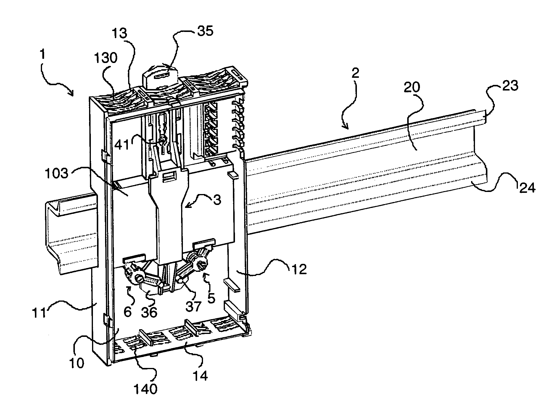
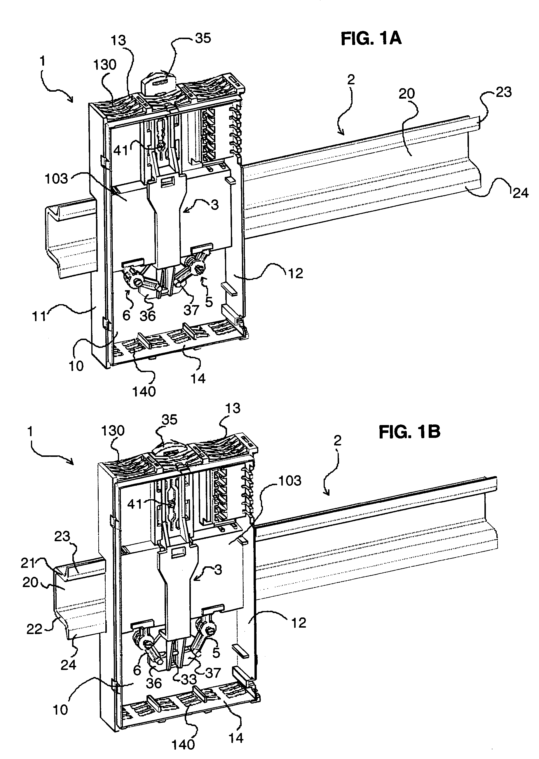
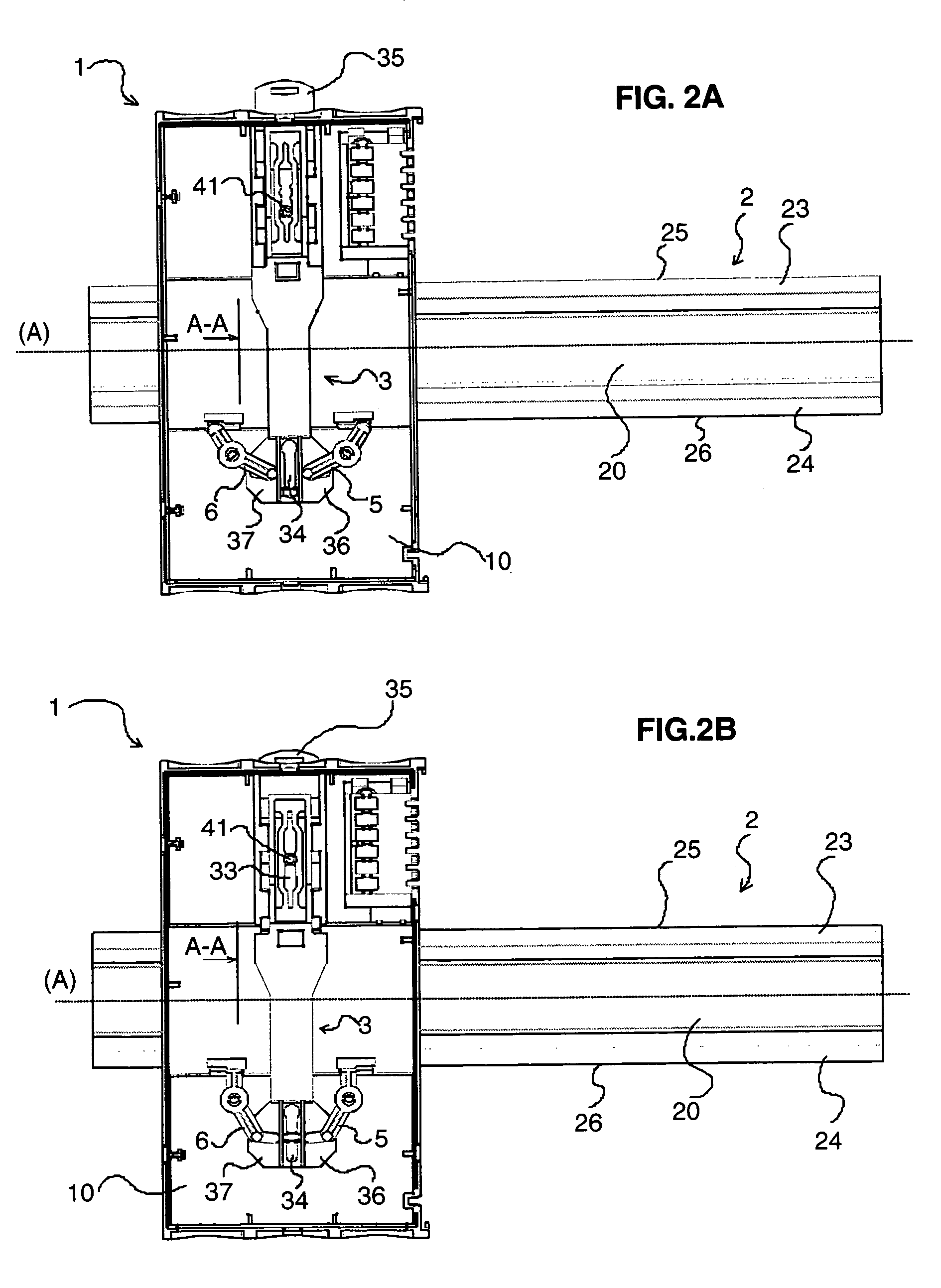
[0035]The invention consists of a device for attaching an electric apparatus 1 onto a supporting rail 2. This supporting rail 2 extends along a main axis (A), is extruded and bent so as to have a hat-shaped cross section. It has a central web 20 connected to two parallel flanges 21, 22, bent so as to form two raised edges 23, 24 situated in one and the same plane either side of the central web. The top raised edge 23 of the rail forms a top edge 25 and the bottom raised edge 24 of the rail forms a bottom edge 26. The rail may support several electric apparatus placed adjacent to and where necessary connected to one another.

[0036]The electric apparatus 1 comprises a casing having a front panel (not shown), a rear panel 10, two side panels 11, 12, a top panel 13 and a bottom panel 14. The rear panel 10 has a recess 103 forming a guide passageway at the bottom of which the two raised edges 23, 24 of the rail 2 come to bear. This guide passageway is formed over the whole width of the ca...


PUM


Abstract

A device for locking an electric apparatus to a supporting rail with two opposite raised edges, the device including a first attachment unit configured to be connected with a first raised edge of the supporting rail; a second attachment unit configured to be connected with a second opposite raised edge of the supporting rail, configured to be movable in an unlocked position; and an operating element connected to the first and second attachment units and configured to convert a translation movement of the first attachment unit into a rotary movement of the second attachment unit, the second attachment unit including a rod that is configured to perform the rotary movement when actuated by the translation movement of the operating element.

Description

BACKGROUND OF THE INVENTION[0001](1) Field of the Invention[0002]The present invention relates to a device for attaching an electric apparatus onto a supporting rail with two opposite raised edges. The invention is particularly suitable for the attachment of an electric apparatus onto a DIN rail.[0003](2) Description of the Related Art[0004]U.S. Pat. No. 5,775,955 reveals a device for attaching an electronic module onto a DIN rail having two opposite coplanar raised edges. The attachment device comprises two distinct and independent plates intended to be slid into two lateral openings formed on the body of the module. Each plate makes it possible to come and lock the module onto a raised edge of the rail. In this patent, the attachment of the module is not very practical because it requires two successive manipulations.[0005]Also known via U.S. Pat. No. 5,704,805 is a device for attaching an electric apparatus onto a DIN rail having two opposite raised edges comprising a single cont...

Claims


Application Information

Patent Timeline
IPC IPC(8): A47B96/00
CPCH01R9/2608H02B1/052H02B1/0523
Inventor PORTAL, ALEX
Owner SCHNEIDER ELECTRIC IND SAS
Why Eureka
Try Eureka