
Seat adjusting mechanism of a motorized wheelchair

a motorized wheelchair and seat adjustment technology, which is applied in the direction of wheelchair/patient conveyance, transportation and packaging, lifting devices, etc., can solve the problems of not having the function to control the seat, occupying a lot of space, and difficult driving in transportation, so as to improve the stability of the seat up-down adjustment and the aesthetics of the wheelchair, and move the seat smoothly up and down. , the effect of minimizing the needed spa

Active Publication Date: 2009-04-14
CYCLING & HEALTH TECH IND R & D CENT
View PDF9 Cites 15 Cited by
  • Summary
  • Abstract
  • Description
  • Claims
  • Application Information

AI Technical Summary

Benefits of technology

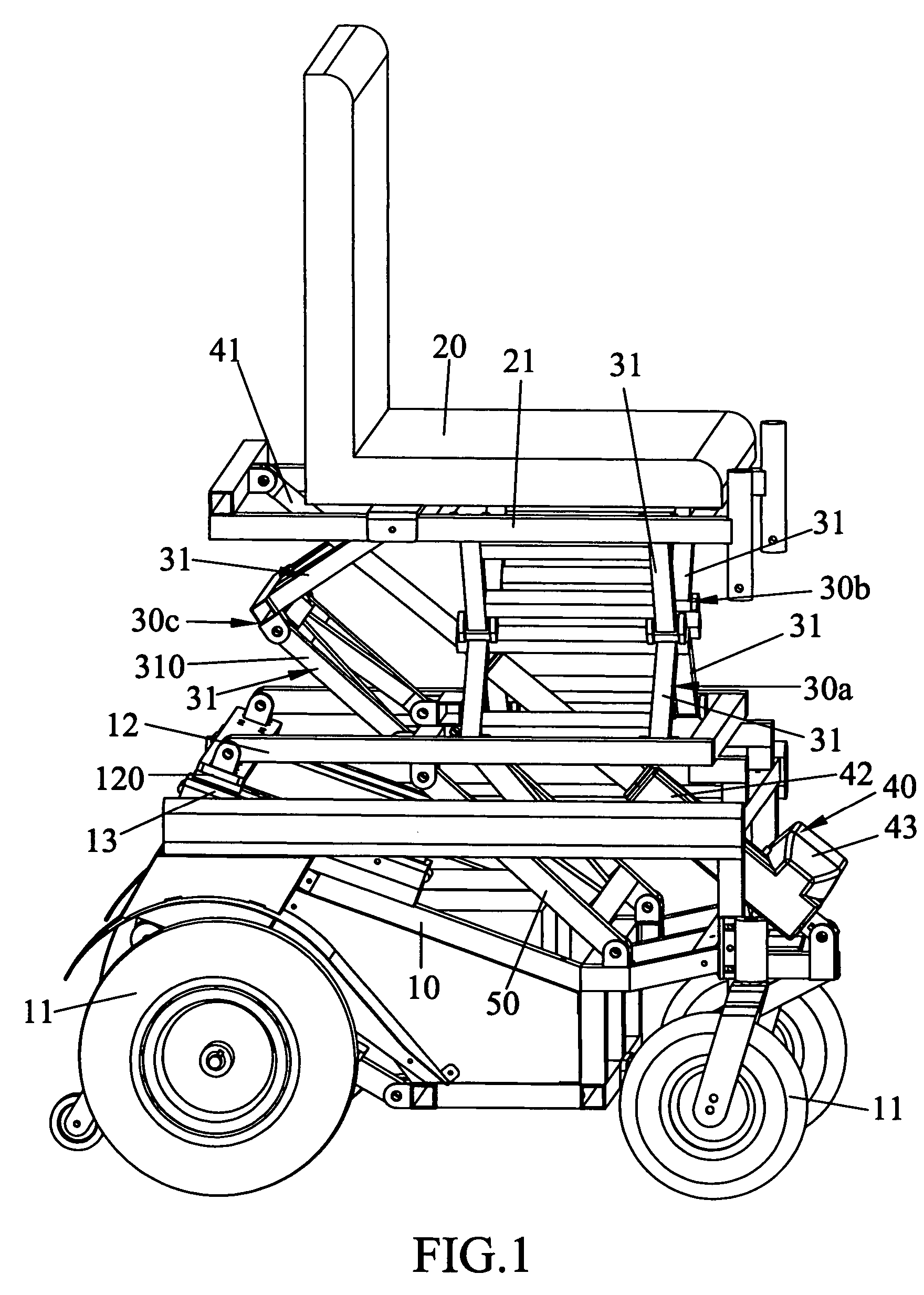
[0004]The purpose of this invention is to enhance the stability of the seat up-down adjustment and the aesthetics of a wheelchair. The mechanism is structured by the cart frame, the seat, the linking rod mechanism and the linear motion actuator. There are at least two linking rod mechanisms, each mechanism is composed of several connecting rods in even number and pivot-linked with each others, and connected to the cart frame and the seat at the two ends. The linear motion actuator connects a cart frame and a seat, moves the seat up and down smoothly with help from the stable supporting of the linking rod mechanism. The whole adjustment mechanism is confined in between a seat and a cart frame, which minimizes the needed space and makes a nice figure.

Problems solved by technology

However, the current common seen wheelchair seat adjusting mechanism moves the seat up and down by a simple linking rod with actuator, e.g. U.S. Pat. No. 5,924,720, the seat is up-down adjustable with a 4 linking-rod mechanism composed of continuous 2 linking rod in between the cart frame and the seat frame together with a linear motion actuator, this commonly applied mechanism takes a lot of space which makes driving difficult and inconvenient in transportation.
However, it does not have the function to control the seat up and down; furthermore, the guide rail is rising and extending to the front, when the seat is leaned, the height of the seat is increased, which causes unstable, uncomfortable and dangerous to the rider.

Method used


Image

  • Seat adjusting mechanism of a motorized wheelchair
  • Seat adjusting mechanism of a motorized wheelchair
  • Seat adjusting mechanism of a motorized wheelchair

Examples


Embodiment Construction

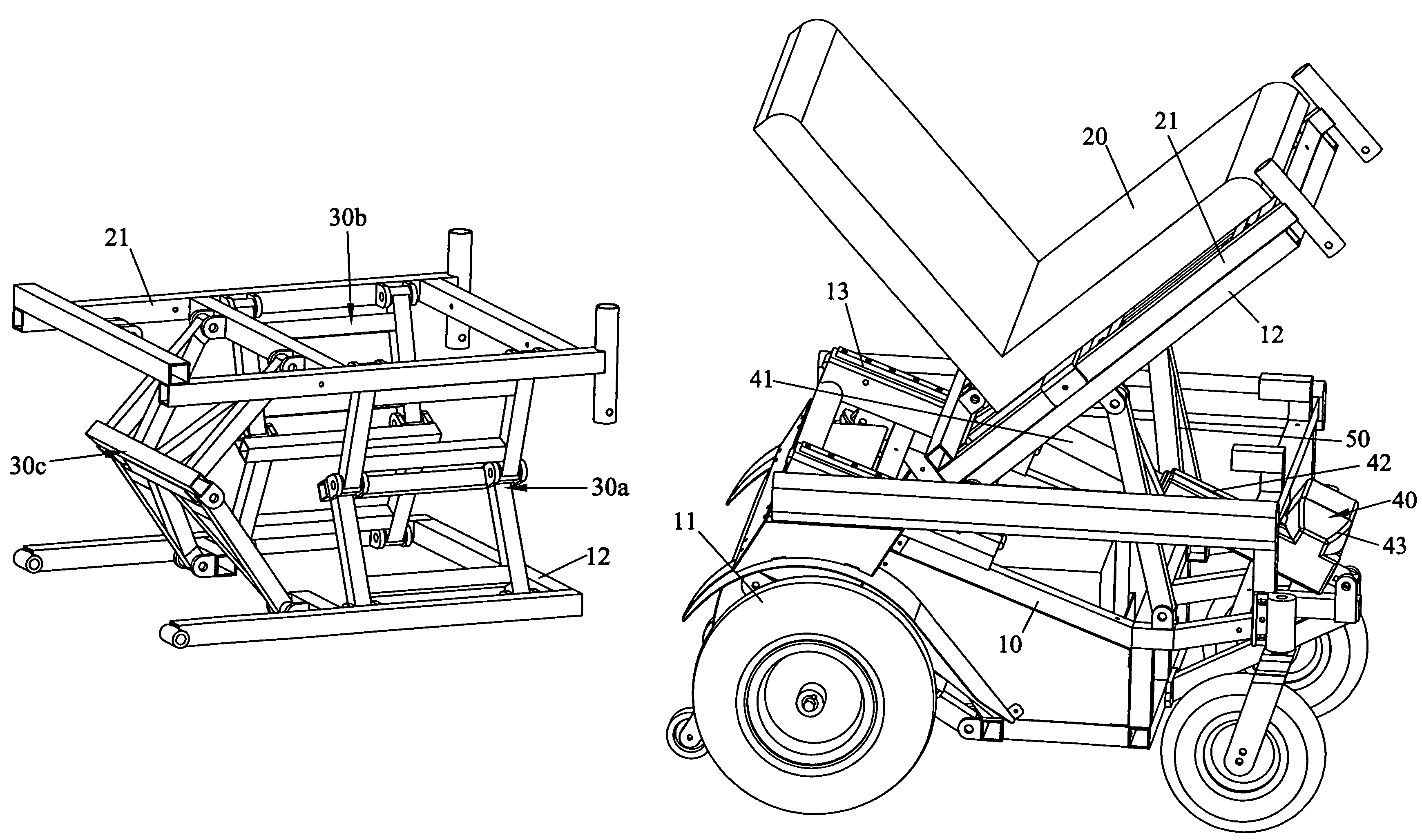
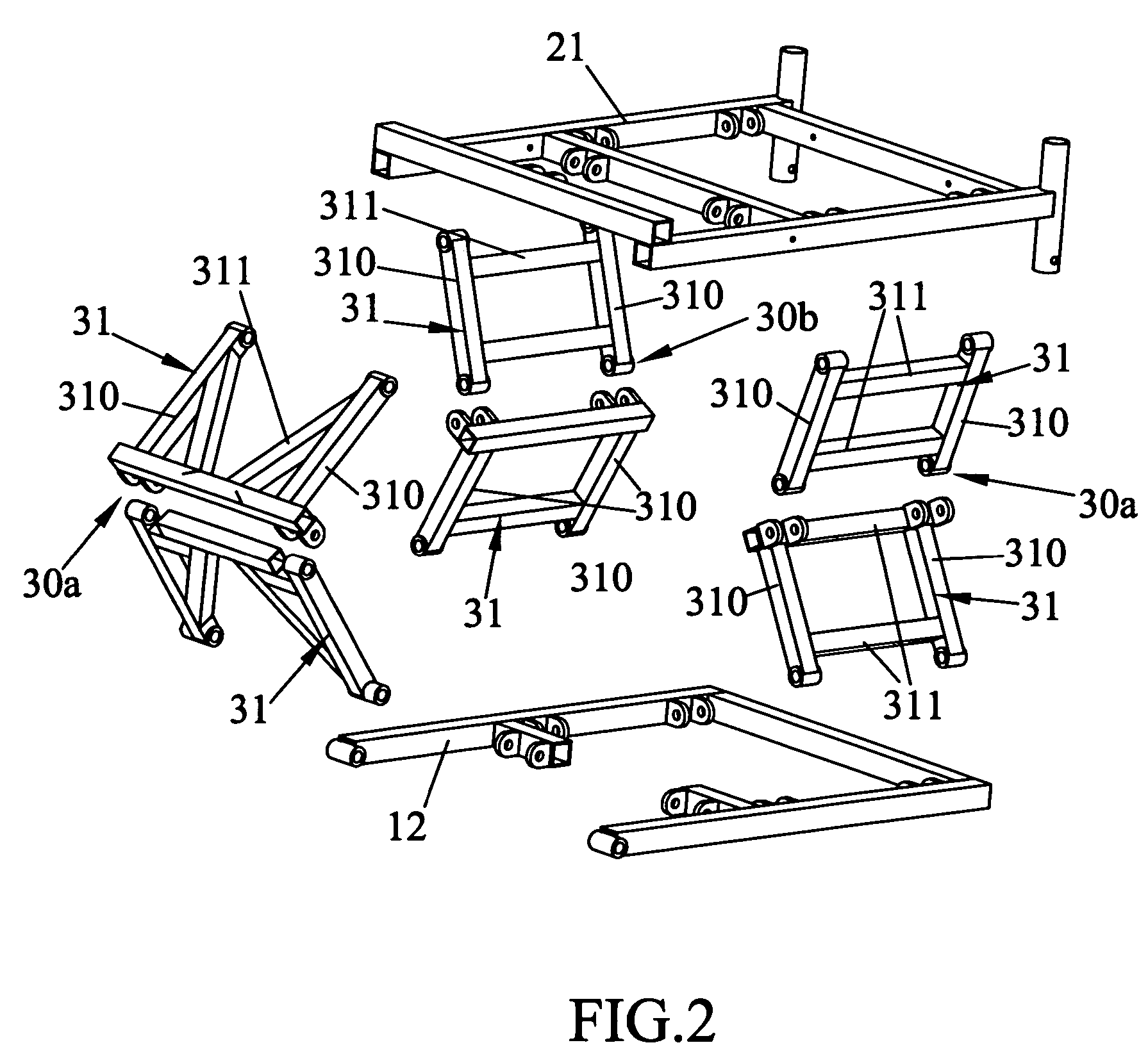
[0012]Referring to FIGS. 1 to 3, the mechanism of this invention can achieve to simply the seat frame, to stabilize the up-down motion, and to minimize the needed space. The basic compositions are:[0013]A cart frame 10, with wheels 11 connected thereon, and having a rear end, a front end and a longitudinal axis extending from the rear end to the front end of the cart frame.[0014]A seat 20.

[0015]A linking rod mechanisms 30a and 30b, each includes plurality connecting frames 31 which are pivot-linked with each others and remains two distal ends, and the two distal ends are respectively connected to the cart frame 10 and the seat 20. In one embodiment of the invention, the cart frame 10 further comprises a primary frame 12, the primary frame 12 is connected to the cart frame 10, the seat 20 is installed on a secondary frame 21, and the two distal ends of the mechanisms 30a / 30b are respectively pivotally connected to the primary frame 12 and the secondary frame 21. One advantage design ...


PUM


Abstract

The purpose of this invention is to enhance the stability of seat up-down adjustment and the aesthetics of a wheelchair. The mechanism is structured by the cart frame, the seat, the linking rod mechanism and the linear motion actuator. There are at least two linking rod mechanisms, each mechanism is composed of several connecting frames and pivot-linked with each others and remains two distal ends for connecting to the cart frame and the seat. The linear motion actuator connects the cart frame and the seat, moves the seat up and down smoothly with help from the stable supporting of the linking rod mechanism. The whole adjustment mechanism is confined in between the seat and the cart frame, which minimizes the needed space and makes a nice figure.

Description

FIELD OF THE INVENTION[0001]This present invention relates to a seat adjusting mechanism of a motorized wheelchair, specifically a kind of linking rod mechanism which is structured by a cart frame, a seat and plurality connecting frames pivot-linked with each others, the seat moves smoothly up and down relatively to the cart frame, driven by a linear motion actuator, the linking rod mechanism is hidden in a way of nice figure.BACKGROUND OF THE INVENTION[0002]There are varieties of wheelchairs, most of the conventional wheelchairs do not have seat adjusting mechanisms, recently to enhance convenience and comfort in use, some seats are designed with up-down adjustable or lean adjustable mechanism. However, the current common seen wheelchair seat adjusting mechanism moves the seat up and down by a simple linking rod with actuator, e.g. U.S. Pat. No. 5,924,720, the seat is up-down adjustable with a 4 linking-rod mechanism composed of continuous 2 linking rod in between the cart frame an...

Claims


Application Information

Patent Timeline
Patent Type & Authority Patents(United States)
IPC IPC(8): B62B1/00
CPCA61G5/045A61G5/1059A61G5/107A61G5/1075
Inventor WU, HUNG-SHENGJU, SHUN-YUAN
Owner CYCLING & HEALTH TECH IND R & D CENT
Learn More