Electric valve

A technology of electric valve and valve shaft, applied in the direction of lift valve, valve details, valve device, etc., to reduce leakage, improve durability, and improve seating stability.

Active Publication Date: 2017-12-29
SAGINOMIYA SEISAKUSHO INC
View PDF1 Cites 0 Cited by
  • Summary
  • Abstract
  • Description
  • Claims
  • Application Information

AI Technical Summary

Problems solved by technology

In such a case, a problem arises in correctly performing flow control with the spool 12 and the valve seat 13

Method used


Image

  • Electric valve
  • Electric valve
  • Electric valve

Examples


Embodiment Construction

[0062] Hereinafter, preferred embodiments of the present invention will be described with reference to the drawings.

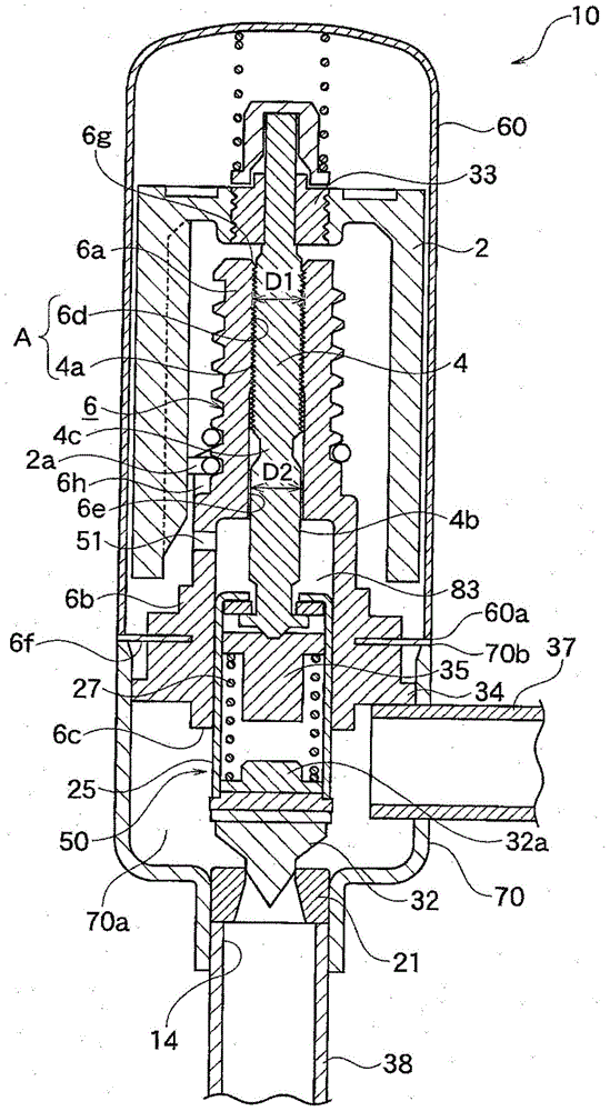
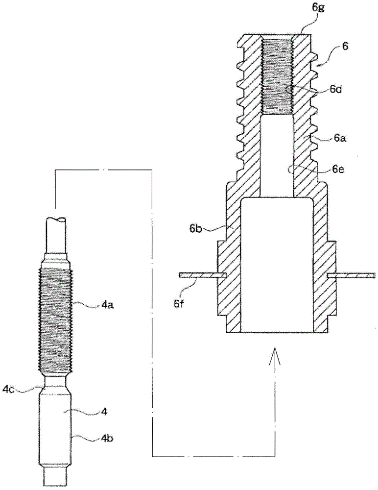
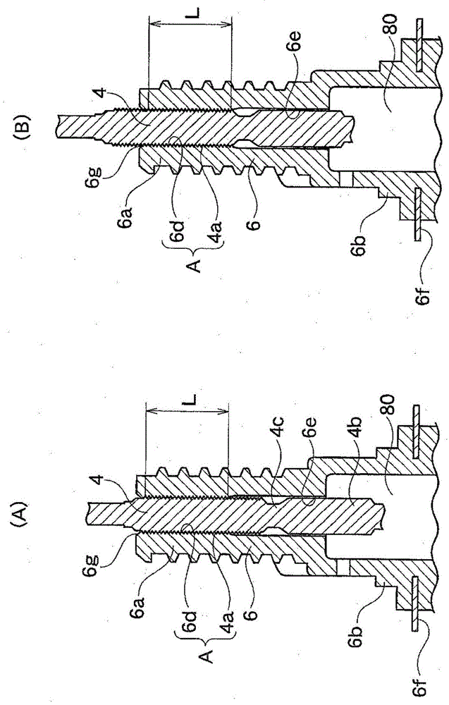
[0063] figure 1 It is a cross-sectional view showing an electric valve according to a preferred embodiment of the present invention, figure 2 yes means figure 1 A schematic diagram of the assembly form of the valve shaft and the valve shaft bracket in the electric valve shown.

[0064] In addition, in this specification, "upper" or "lower" means figure 1 specified by the state.

[0065] In this electric valve 10 , a valve chamber forming member 70 is integrally connected by welding to the lower end portion on the opening side of a cylindrical cup-shaped case 60 made of a non-magnetic material.

[0066] In the valve chamber 70 a of the valve chamber forming member 70 , the first joint 38 is connected downward (axially), the second joint 37 is connected to the side, and the input and output ports of the valve chamber forming member 70 connected to the fi...


PUM


Abstract

The invention provides an electric valve, and the electric valve can enable a valve core which moves up and down to abut against a valve seat at a stable posture. The electric valve (10) is provided with a thread feeding mechanism (A) which enables the rotating movement of a rotor (2) to be changed into linear movement. The electric valve (10) is characterized in that C1 is less than C2 when the external diameter of an external thread part (4a) of a valve shaft (4) is set as C1 and the internal diameter of the lower side of a spiral spring (27) relative to a sitting part of a spring bottom (32a) is set as C2.

Description

technical field [0001] The present invention relates to a stepping motor-driven electric valve for controlling the flow rate of refrigerant in a refrigeration cycle or the like. Background technique [0002] In stepping motor-driven electric valves used as variable throttle valves, flow control valves, etc., the rotary motion of the rotor of the electric motor is converted into the motion of the valve shaft by a screw feed mechanism composed of internal threads and external threads. In the linear motion, the valve is opened and closed by moving a valve body disposed below the valve shaft relative to the valve seat (for example, Patent Document 1). [0003] Figure 5 (A), Figure 5 (B) shows such a conventional electric valve 20A. [0004] In this motor-operated valve 20A, an external thread portion 5 (movable thread portion) formed on the outer periphery of the valve shaft 3 and an internal thread portion 8 (fixed thread portion) formed on the inner periphery of the valve s...

Claims


Application Information

Patent Timeline
Patent Type & Authority Patents(China)
IPC IPC(8): F16K1/32F16K1/02F16K31/04F16K31/50
CPCF16K1/02F16K1/32F16K31/042F16K31/502F16K31/504
Inventor 中川大树小林一也
Owner SAGINOMIYA SEISAKUSHO INC
Why Eureka
Try Eureka