
Chair frame with high strength and high stability

a high-strength, high-strength technology, applied in the field of mechanical design, can solve the problems of affecting the stretching, upward and downward movements of the seat, the seat tends to be unstable, and the seat is more unstable, so as to achieve the effect of increasing the weight support capacity of the seat, high strength and high stability

Inactive Publication Date: 2019-09-03
TAIZHOU LUCKY PRETTY MACHINERY CO LTD
View PDF14 Cites 1 Cited by
  • Summary
  • Abstract
  • Description
  • Claims
  • Application Information

AI Technical Summary

Benefits of technology

[0008]According to the problems in the prior art, the invention aims to provide an improved multifunctional chair frame, so that the difficulty in machining of the chair frame can be reduced while the improved multifunctional chair frame has a high stability and an excellent load bearing strength.
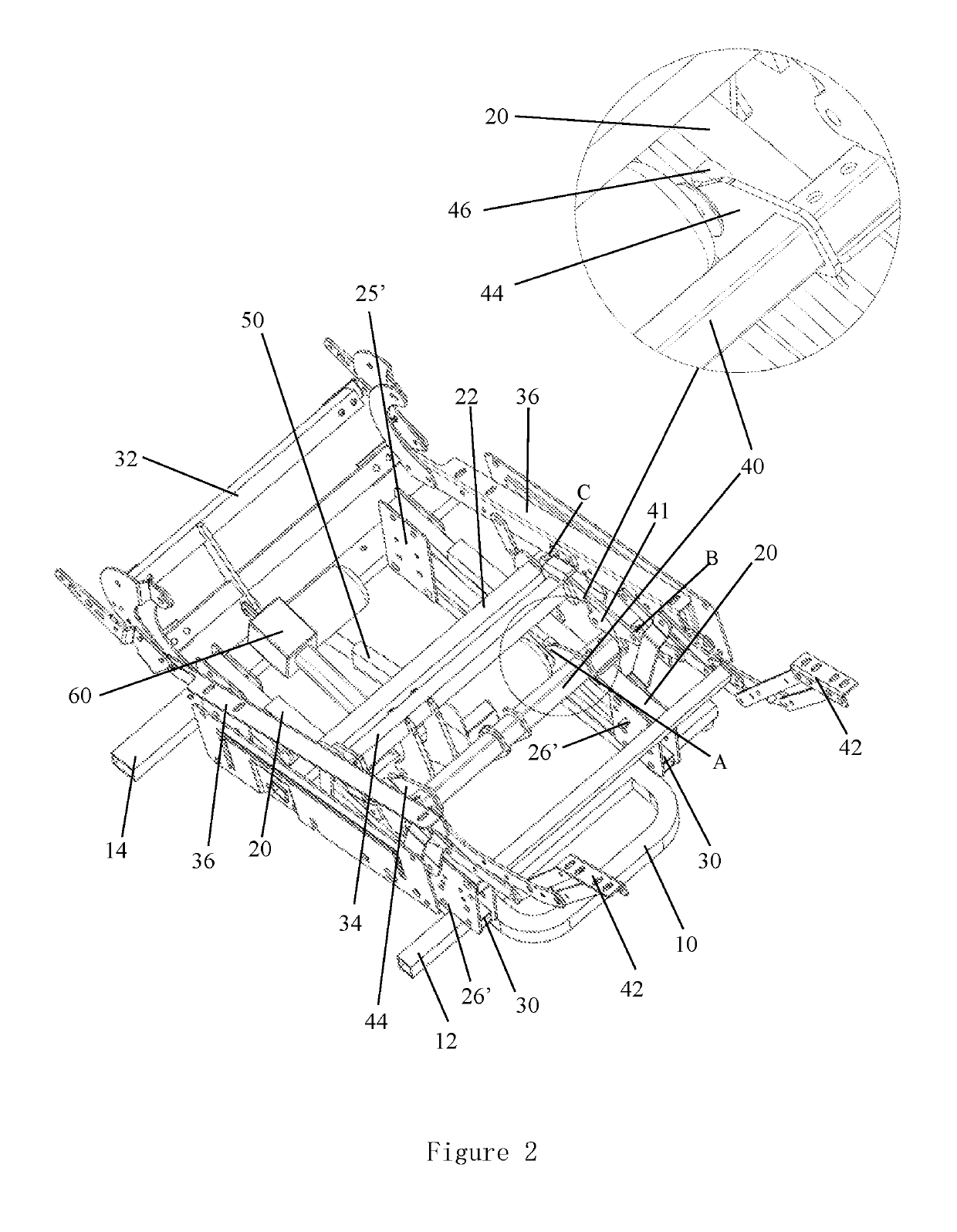
[0009]To achieve the objectives of the invention, the invention provides a chair frame having a high stability and a high load bearing strength, including a base, wherein the base includes a base front supporting tube, a base rear supporting tube, a base right supporting tube and a base left supporting tube, a pedal support is connected to a front driving tube through a connecting rod mechanism, one end of a main motor telescopic rod mechanism is fixedly connected to the front driving tube, and the other end of the main motor telescopic rod mechanism is fixedly connected to the base rear supporting tube; a left handrail support and a right handrail support are fixed to a left end of a backrest front driving tube and a right end of the backrest front driving tube, and the backrest front driving tube is connected to the front driving tube through a connecting rod mechanism, one end of a backrest motor telescopic rod mechanism is fixedly connected to the backrest front driving tube, and the other end of the backrest motor telescopic rod mechanism is fixedly connected to a backrest rear driving tube; a front end of an upper frame is fixedly connected to an upper portion of a connecting piece, and a front end of a lower frame is connected to a lower portion of the connecting piece through a rivet, and a rear end of the lower frame is connected to a connecting piece through a rivet, a rear end of the base left supporting tube and a rear end of the base right supporting tube are fixedly connected to a lower portion of the connecting piece, each of two sides of the front driving tube is further connected to a clamping piece, and a clamping pin structure matched with the clamping piece is fixed on the upper frame.
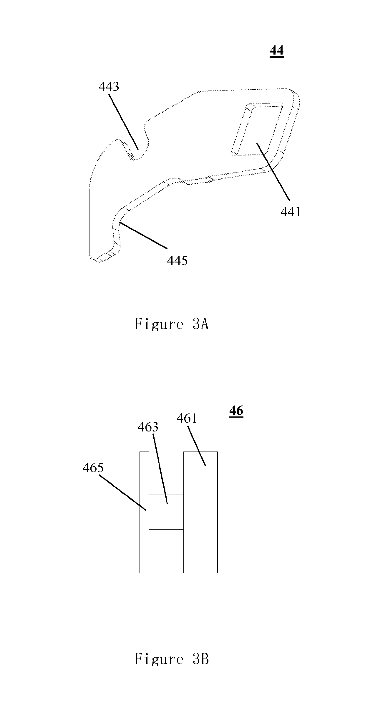
[0019]As to the chair frame having a high strength and high stability, a set of clamping pin connecting structures are additionally arranged between each of two ends of the front driving tube and the upper frame. The clamping pin connecting structures, the upper frame of the chair frame, the base left supporting tube, the base right supporting tube, and the connecting rod mechanism are not in the same plane and a three-point fixed pressure-bearing structure in the space is formed. When a user sits on the chair, and the weight of the body can be transmitted to the chair frame base through the pressure-bearing structure firstly, and the extra weight can be transmitted to a pressure bearing structure of the motor telescopic rod mechanism, so that weight supporting capability of the seat is greatly increased, the stability of the seat is improved, and the motor telescopic rod mechanism is effectively protected. The connecting structure between the upper frame and the fixed connecting piece of the upper frame, and the connecting structure between the left and right supporting tubes of the chair frame and the fixed connecting piece are improved and designed, which improves the precision of welding fixation, and the load bearing strength and stability of the connection structure.

Problems solved by technology

On one hand, the connecting rod mechanism is always connected in a riveting mode, and when too large force is applied to the connecting rod mechanism, the seat tends to be unstable.
The deformation of the connecting rod mechanism can be caused after a long period making the seat more unstable.
The deformation and bending of the motor telescopic rod can be caused after a long period, thus hindering the stretching and upward and downward movements of the seat, impacting the use by the user.
Furthermore, when the weight of the user is too large, it may cause the telescopic rod of the motor to break, so that the seat loses the corresponding functions.
These cause quality defects of the product and even damages to the user.
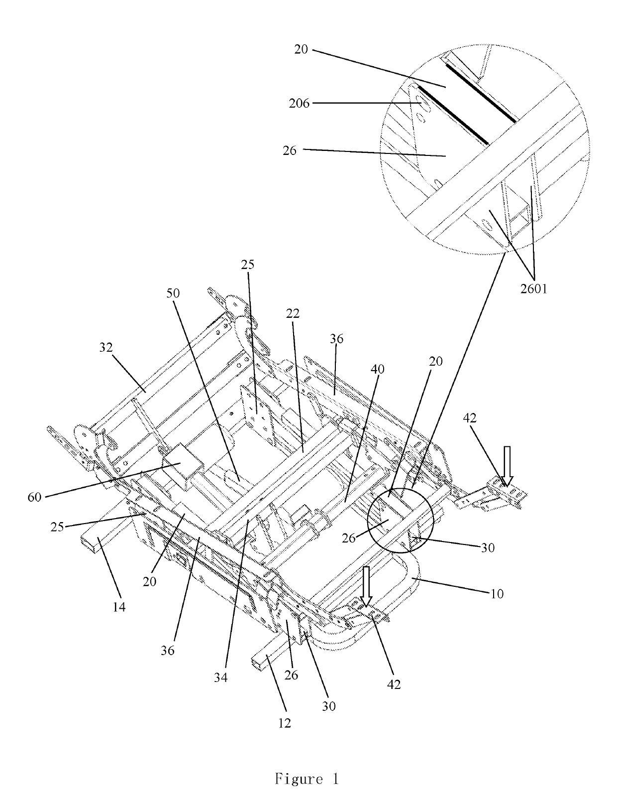
This connecting and fixing mode has several problems.
Due to the fact that all the components which are matched with each other unavoidably have the size tolerances, the top surface of the upper frame 20 and the connecting plate 2601 cannot be completely aligned during welding, which increases the difficulty in welding.
It is difficult to ensure that the two connecting plates 2601 can be accurately positioned with the upper frame 20, which easily results in a poor welding quality and being scrapped.

Method used


Image

  • Chair frame with high strength and high stability
  • Chair frame with high strength and high stability
  • Chair frame with high strength and high stability

Examples


Embodiment Construction

[0030]The structural features and advantages of the present invention are described in detail with reference to the drawings.

[0031]Referring to FIG. 2, a structural diagram of a chair frame for a multifunctional seat according to an embodiment of the present invention is shown, wherein the chair frame includes a base 10. The base 10 includes a base front supporting tube 12 and a base rear supporting tube 14, a base right supporting tube 16 and a base left supporting tube 18 (see FIG. 4). A pair of pedal supports is connected to the front driving tube 40 through a connecting rod mechanism. One end of the main motor telescopic rod mechanism 50 is fixedly connected to the front driving tube 40, and the other end of the main motor telescopic rod mechanism 50 is fixedly connected to the base rear supporting tube 14. The left handrail support 36 and the right handrail support 36 are connected and fixed to the left end and the right end of the backrest front driving tube 34, and the backre...


PUM


Abstract

This invention provides a chair frame with high strength and high stability, including a base front supporting tube, a base rear supporting tube, a base right supporting tube and a base left supporting tube. A pedal support is connected to a front driving tube through a connecting rod mechanism. Two ends of a main motor telescopic rod mechanism are respectively fixed to the front driving tube and the base rear supporting tube. Two ends of a backrest motor telescopic rod mechanism are fixedly connected to a backrest front driving tube and a backrest rear driving tube. An upper frame is fixedly connected to a connecting piece thereof. The base right supporting tube and the base left supporting tube are fixedly connected to a connecting piece thereof. Two sides of the front driving tube are further connected to a clamping piece.

Description

CROSS REFERENCE TO RELATED APPLICATIONS[0001]This application is based upon and claims priority to Chinese Patent Application No. CN2017101639162, filed on Mar. 20, 2017, the entire content of which is incorporated herein by reference.TECHNICAL FIELD[0002]The invention relates to the technical field of mechanical design, particularly to a chair frame with high strength and high stability.BACKGROUND OF THE INVENTION[0003]The multifunctional chair can be unfolded as a reclining chair or a massage chair, and the multifunctional chair can also move up and down as a general office or household seat after being retracted, so that a plurality of use requirements can be brought to people, and therefore, the method is popular among a great number of users. The chair frame of the multifunctional chair generally includes a seat part and a pedal part which can be unfolded or retracted. A motor telescopic rod mechanism and a plurality of connecting rod structures are installed below the chair fr...

Claims


Application Information

Patent Timeline
Patent Type & Authority Patents(United States)
IPC IPC(8): A47C1/024A61G5/14A47C5/04
CPCA61G5/14A47C1/0242A47C5/04A47C7/002A47C7/02
Inventor MA, MINGYANG
Owner TAIZHOU LUCKY PRETTY MACHINERY CO LTD
Learn More