
High-speed electromagnetic valve of high-pressure common-rail oil injector capable of realizing multiple-injection stability

A high-speed solenoid valve and high-pressure common rail technology, applied in fuel injection devices, fuel injection control, electrical control, etc., can solve problems such as rebound and incomplete seating, and achieve improved fuel injection stability, stable closing, and improved seating stability sexual effect

Active Publication Date: 2022-06-17
HARBIN ENG UNIV
View PDF5 Cites 0 Cited by
  • Summary
  • Abstract
  • Description
  • Claims
  • Application Information

AI Technical Summary

Problems solved by technology

[0004]The purpose of the present invention is to provide a method that can solve the rebound and incomplete seating of the armature of the existing high-speed solenoid valve under multiple in

Method used


Image

  • High-speed electromagnetic valve of high-pressure common-rail oil injector capable of realizing multiple-injection stability
  • High-speed electromagnetic valve of high-pressure common-rail oil injector capable of realizing multiple-injection stability
  • High-speed electromagnetic valve of high-pressure common-rail oil injector capable of realizing multiple-injection stability

Examples


Example Embodiment

[0024]下面结合附图举例对本发明做更详细地描述:

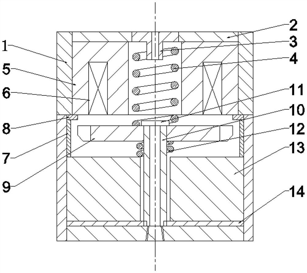
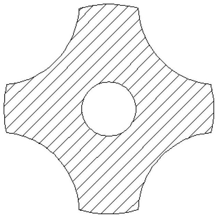
[0025]图1为本发明的结构示意图,包括壳体1、紧固螺母2、电磁阀复位弹簧座3、电磁阀复位弹簧4、铁芯5、线圈6、固定垫片7、缓冲调节垫片8、衔铁9、衔铁阀杆10、阀杆紧固螺母11、缓冲弹簧12、阀座13、缓冲调节环带14,铁芯5凹槽中安装有线圈6,中间通孔里安装有电磁阀复位弹簧4,电磁阀复位弹簧4一端固定在电磁阀复位弹簧座3上,另一端被衔铁9上端顶住,衔铁阀杆10上端与衔铁9通过衔铁紧固螺母11连接,衔铁阀杆10中间开有回油油路,缓冲弹簧12套在衔铁阀杆10上端,置于衔铁9与阀座13中间,衔铁9外缘设有四个弧形切面,所述缓冲调节垫片8设在固定垫片7与铁芯5之间,所述阀杆10下端外缘设有四个垂直切面,所述阀座13开有通孔,通孔内径大于阀杆10外径,阀座13下方设有缓冲调节环带14。缓冲调节垫片8内径小于固定垫片7内径,大于衔铁9外径,与衔铁9外缘形成0.004-0.006mm的上升节流阻尼间隙15,缓冲调节环带14内径大于阀杆10外径,与阀杆10下端外缘形成0.005-0.007mm的落座节流阻尼间隙16。缓冲调节垫片8下端高度低于衔铁9的最大位移处,缓冲调节垫片8下端高度位于衔铁9上升总行程的80%处,缓冲调节环带14上端高度高于阀杆10下端的初始位置,缓冲调节环带14上端高度位于衔铁9落座总行程的80%处。

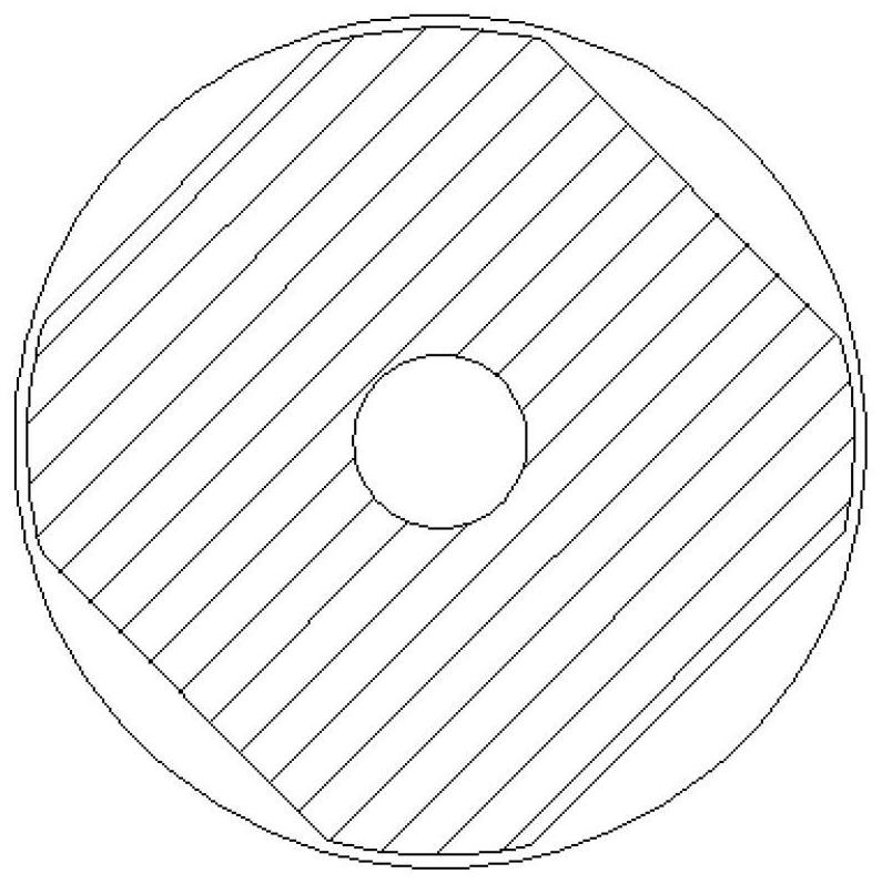
[0026]结合图2-5,本发明的工作原理为,当电磁阀的线圈6不通电时,电磁阀复位弹簧4处于压缩状态,对衔铁9产生一个向下的弹簧力,缓冲弹簧12同样处于压缩状态,对衔铁9产生一个向上的弹簧力,但电磁阀复位弹簧4的弹簧力大于缓冲弹簧12的弹簧力,因此衔铁9在合力的作用下保持在初始位置。当电磁阀的线圈6通电时,同铁芯5和衔铁9形成磁回路,对衔铁9产生电磁力,衔铁9带动衔铁阀杆10一起向上运动,回油油路开启,低压燃油通过衔铁阀杆通孔和衔铁阀杆10外侧泄走。当衔铁9向上运动至与缓冲调节垫片8下端高度齐平时,衔铁9外缘与缓冲调节垫片8产生节流阻尼效应,燃油流通面积骤然缩小至如图4中阴影所示,导致衔铁9上、下两部分的燃油流通面积迅速减小,燃油不能快速通过并受到挤压,这部分燃油压力急剧上升,对衔铁9上升产生阻力,使衔铁9的上升速度下降,降低衔铁9与铁芯5的碰撞,削弱衔铁9碰撞后的反弹,实现高速电磁阀稳定打开。当电磁...


PUM


Abstract

The high-speed electromagnetic valve comprises a shell, an iron core, an armature, a valve rod and a valve seat, a fastening nut is installed on the upper portion of the shell, an electromagnetic valve reset spring seat is arranged in the middle of the fastening nut, the iron core is installed in the shell, a coil is wound in a groove of the iron core, and an electromagnetic valve reset spring is arranged on the armature. A middle through hole is formed in the middle of the iron core, the electromagnetic valve reset spring is installed in the middle through hole, the armature and the valve seat are sequentially arranged below the iron core, the top of the valve rod is installed in the armature through the valve rod fastening nut, the bottom of the valve rod is located in the through hole of the valve seat, and the electromagnetic valve reset spring seat and the valve rod fastening nut are arranged at the two ends of the electromagnetic valve reset spring respectively. A buffer spring is sleeved on the valve rod between the armature and the valve seat, and an oil return path is arranged in the valve rod. The problems that an armature of an existing high-speed electromagnetic valve rebounds and is not completely seated under multiple times of injection are solved, and the oil injection stability of the common-rail oil injector is improved.

Description

technical field [0001] The invention relates to a diesel engine, specifically a high-pressure common rail device for a diesel engine. Background technique [0002] The high-speed solenoid valve is the core control component of the high-pressure common rail injector. Its dynamic response characteristics directly affect the precise control of the high-pressure common rail injector's cyclic fuel injection volume, fuel injection pattern and fuel injection time, especially for multiple injections. Strategy. Therefore, high dynamic response characteristics are one of the main indicators to measure the performance of high-speed solenoid valves. In high-pressure common rail systems, not only short opening and closing times are required, but also high-speed solenoid valves are required to open stably and close completely. [0003] In order to achieve rapid opening of the high-speed solenoid valve, high voltage is usually used to achieve a rapid rise in the electromagnetic force duri...

Claims


Application Information

Patent Timeline
IPC IPC(8): F02M63/00F02M63/02F02M51/06F02M61/16F02D41/40
CPCF02M63/0022F02M63/007F02M63/0225F02M51/0625F02M61/16F02D41/402
Inventor 赵建辉陈文菲徐煜张恒刘伟龙
Owner HARBIN ENG UNIV
Learn More