Cutting inserts and indexable insert cutting tools

A technology of cutting inserts and inserts, used in milling cutting inserts, manufacturing tools, milling cutters, etc., can solve problems such as wedge angle or clearance angle limitation, and achieve the effect of improving seating stability

Active Publication Date: 2019-09-27
MITSUBISHI MATERIALS CORP
View PDF7 Cites 0 Cited by
  • Summary
  • Abstract
  • Description
  • Claims
  • Application Information

AI Technical Summary

Problems solved by technology

Therefore, there is a problem that the wedge angle or relief angle of the minor cutting edge 7 is easily restricted.

Method used


Image

  • Cutting inserts and indexable insert cutting tools
  • Cutting inserts and indexable insert cutting tools
  • Cutting inserts and indexable insert cutting tools

Examples


no. 1 Embodiment approach >

[0084] Below, refer to Figure 1 to Figure 16 , the indexable insert type cutting tool 1 and the cutting insert 3 according to the first embodiment will be described.

[0085] 〔Outline structure of indexable insert cutting tool〕

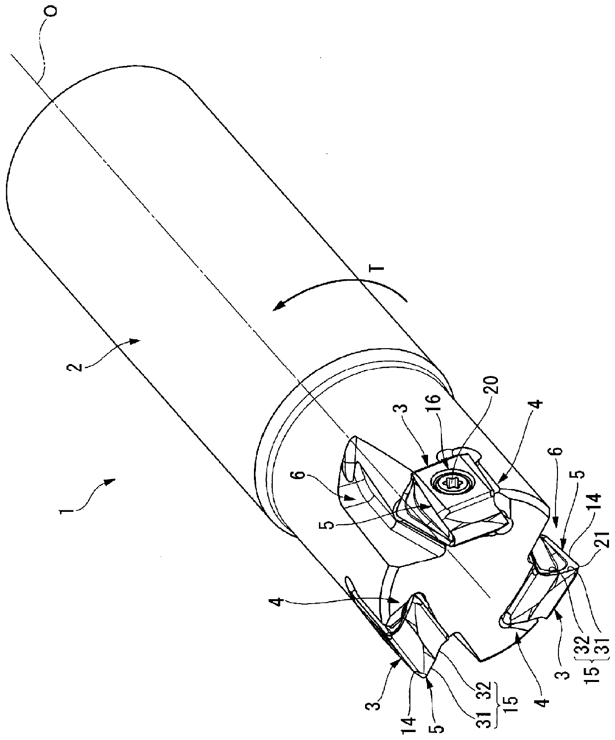
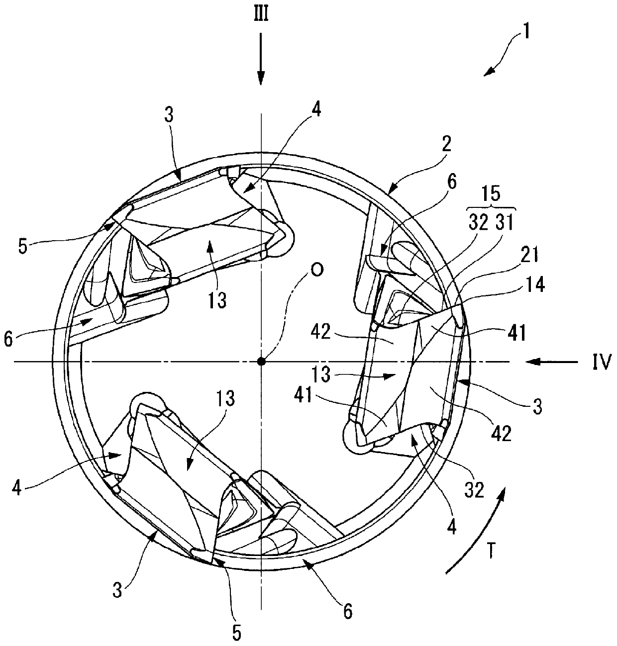
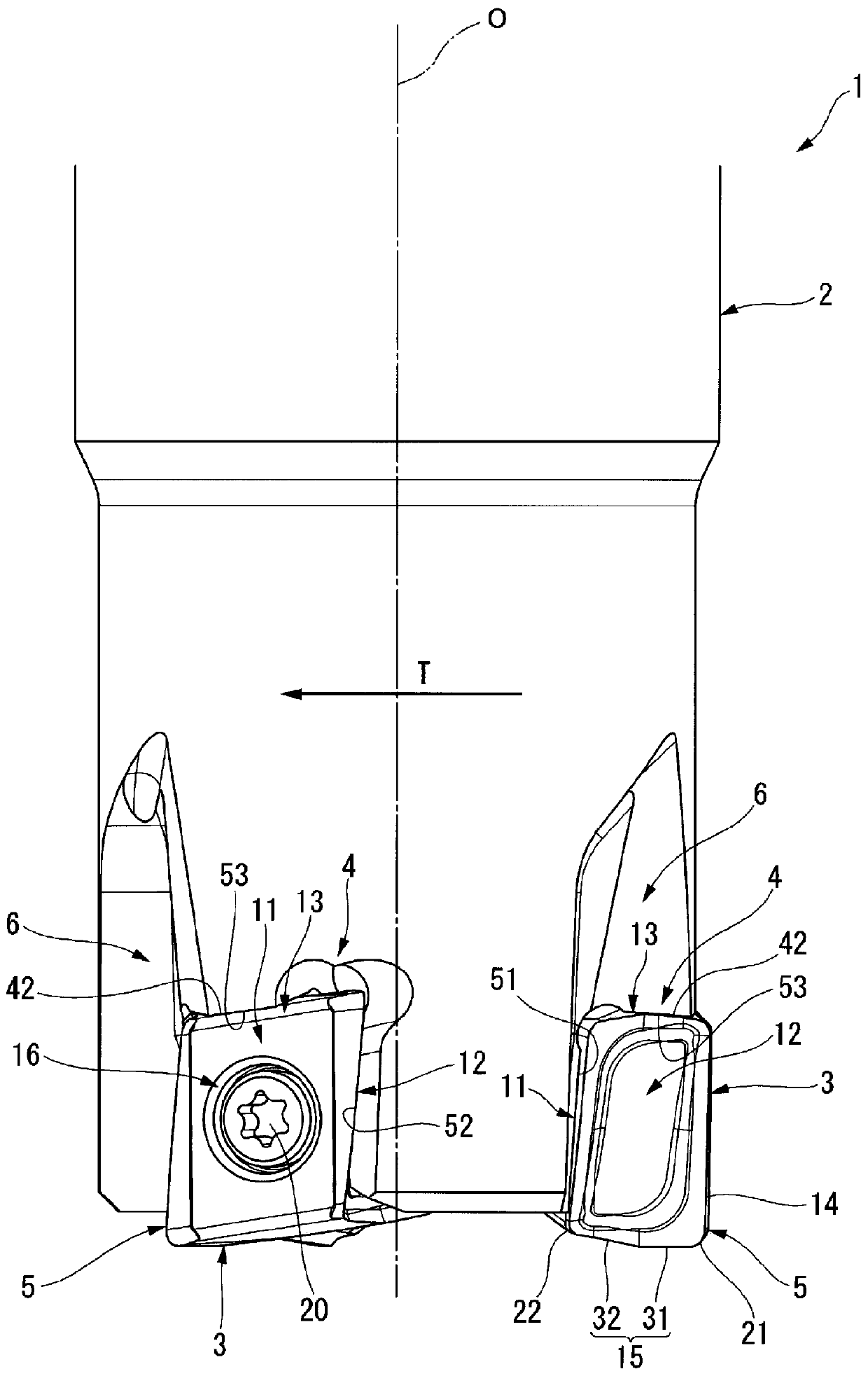
[0086] Such as Figure 1 to Figure 4 As shown, the indexable insert cutting tool 1 of this embodiment includes a tool body 2 formed of steel or the like, and a cutting insert 3 formed of a hard material such as cemented carbide. A concave insert mounting seat 4 is formed on the outer peripheral portion of the front end of the tool body 2 that rotates around the tool axis O. As shown in FIG. A cutting insert 3 having a cutting edge 5 is detachably attached to the insert mounting seat 4 .

[0087] Such as Figure 5 to Figure 8 As shown, the cutting insert 3 is a so-called vertical double-sided cutting insert. The cutting insert 3 has a rectangular plate shape, and is formed in a front-back and reverse-symmetric shape. The cutting insert 3 include...

no. 2 Embodiment approach >

[0205] Next, refer to Figure 17 and Figure 18 , the cutting insert 30 of the indexable insert cutting tool according to the second embodiment will be described.

[0206] Note that detailed descriptions of components that are the same as those in the aforementioned embodiment will be omitted, and only differences will be described below.

[0207] [Differences from the previous embodiment]

[0208] The indexable insert type cutting tool of this embodiment is the same as the tool body 2 of the indexable insert type cutting tool 1 described in the above-mentioned embodiment, but the cutting insert 30 is different. Specifically, in the cutting insert 30, the structure of the short side surface 13 is mainly different.

[0209] Such as Figure 17 and Figure 18 As shown, in the cutting insert 30 of the present embodiment, a pair of first minor cutting edges 31 extending from both end edges of the short side surface 13 in the insert long side axis C2 direction extend toward opp...

no. 3 Embodiment approach >

[0219] The cutting insert 130 of the indexable insert cutting tool according to the third embodiment of the present invention will be described. Figure 20 It is a cross-sectional view of an indexable insert tool to which the cutting insert 130 according to the third embodiment is mounted. and, Figure 21 yes Figure 20 Enlarged view of region XXI of .

[0220] Note that detailed descriptions of components that are the same as those in the aforementioned embodiment will be omitted, and only differences will be described below.

[0221]The indexable insert type cutting tool of this embodiment is the same as the tool body 2 of the indexable insert type cutting tool 1 described in the above-mentioned embodiment, but the cutting insert 130 is different. Specifically, the structure of the mounting hole 116 of the cutting insert 130 is different.

[0222] The cutting insert 130 of this embodiment is provided with the mounting hole 116 similarly to the first embodiment. The moun...


PUM


Abstract

The secondary cutting edge (15) has: the 1st secondary cutting edge (31); and the 2nd secondary cutting edge (32). The inner side of the insert in the direction of the short side axis (C3) extends, and the flank surface (42) of the second minor cutting edge (32) moves toward the direction of the insert long side axis (C2) from the second minor cutting edge (32). The outer side of the blade in the direction of the short side axis (C3) of the blade is inclined, and as it moves from the main surface (11) adjacent to the flank (42) to the direction of the main surface axis (C1) of the blade, toward the axis of the short side of the blade (C3) ) direction of the insert outside is inclined, the flank surface (41) of the first minor cutting edge (31) moves from the first minor cutting edge to the direction of the insert long side axis (C2), and the direction of the insert main face axis (C1) The length is reduced, and the flank surfaces (41) of the pair of first minor cutting edges (31) on the short side surface (13) are formed by mutually different planes.

Description

technical field [0001] The present invention relates to a so-called straight edge double-sided cutting insert and an indexable insert type cutting tool in which the cutting insert is detachably attached to an insert mounting seat on the outer peripheral portion of the front end of a tool body rotating around the tool axis. This application claims priority based on Patent Application No. 2015-181680 for which it applied in Japan on September 15, 2015, and uses the content here. Background technique [0002] Conventionally, indexable insert type cutting tools such as indexable insert type milling cutters for cutting workpiece materials made of metal materials and the like are known. [0003] For example, Patent Document 1 below discloses an indexable insert milling cutter in which a cutting insert having a cutting edge is detachably attached to an insert mounting seat formed on the outer peripheral portion of the front end of a tool body rotating around the tool axis. This in...

Claims


Application Information

Patent Timeline
Patent Type & Authority Patents(China)
IPC IPC(8): B23C5/20B23C5/10
CPCB23C5/109B23C2200/125B23C2200/367B23C2200/28B23C5/2213B23C2200/284B23C2200/24B23C2210/202B23C5/10B23C5/20B23C5/2472B23C2200/0438
Inventor 北岛纯古木俊充石森茂山崎喜市萩原隆行
Owner MITSUBISHI MATERIALS CORP
Why Eureka
Try Eureka