Infusion device for medical fluids

a technology of infusion device and fluid, which is applied in the direction of positive displacement liquid engine, piston pump, instruments, etc., can solve the problems of inability to signal a risk of occlusion in the infusion line in good time, relatively slow change in the internal pressure of the syringe, and inability to signal a risk of occlusion in the infusion line, etc., to achieve high reliability, simple and economical construction, and very precise

Active Publication Date: 2009-04-14
GAMBRO LUNDIA AB
View PDF40 Cites 85 Cited by
  • Summary
  • Abstract
  • Description
  • Claims
  • Application Information

AI Technical Summary

Benefits of technology

[0018]An advantage of the invention is that it provides an infusion device, constructionally simple and economical, provided with a system for signalling an insufficient infusion flow which is highly reliable and very precise.
[0019]A further advantage of the invention is that it provides a security system which signals, in good time, an anomalous situation which can be linked to an insufficient infusion flow and / or an overpressure.
[0020]These aims and advantages and more besides are all attained by the object of the invention, as it is characterised in one or more of the appended claims.
[0021]In an embodiment of the invention, the security system signals an anomalous situation if the derivative of a first parameter indicating the infusion force, compared to a second parameter indicating the progression of the infusion, is greater than a maximum threshold.
[0022]In an embodiment of the invention, the infusion force is a linear pushing force, usable for example in an infusion device comprising a pump of a syringe type.
[0023]In an embodiment of the invention, the above-cited second parameter is correlated to the displacement of a mobile part of the device.

Problems solved by technology

The prior art monitoring systems all however exhibit a drawback: they are not able, in good time, to signal a risk of occlusion in the infusion line when the infusion flow rate is very low, as happens for example in an infusion device of an anticoagulant in an extracorporeal circuit.
However, in the case of low infusion flow rates of anticoagulant and / or use of syringes of large dimensions, an occlusion leads to a relatively slow change in the internal pressure of the syringe, and thus to a considerable delay in the alarm signal.
A further cause of delay in alarm signalling is the presence of a low pressure internally of the extracorporeal system, which tends to increase times for reaching the threshold conditions which determine an alarm signalling.

Method used


Image

  • Infusion device for medical fluids
  • Infusion device for medical fluids
  • Infusion device for medical fluids

Examples


Embodiment Construction

Legend of FIGS. 1 and 2.

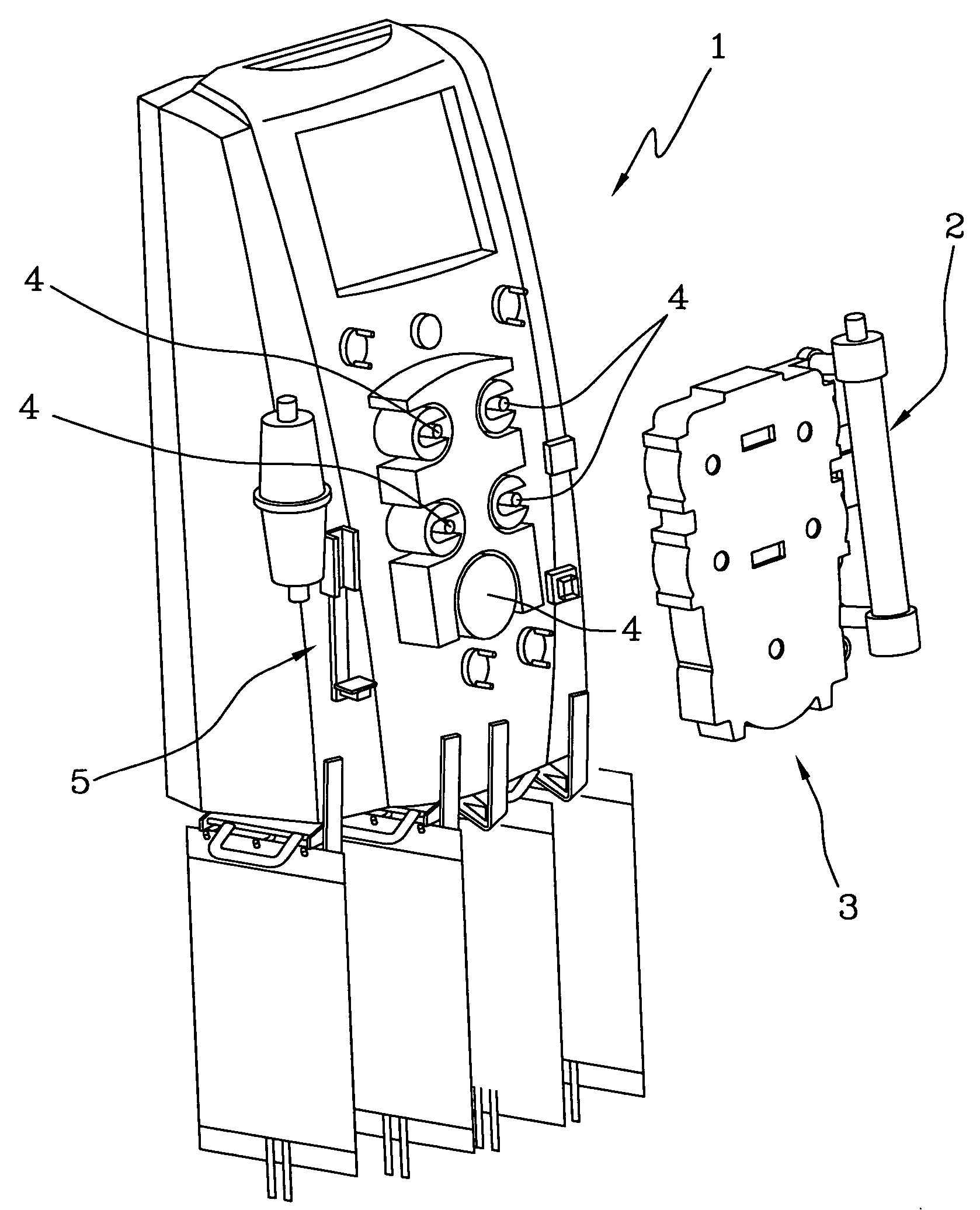
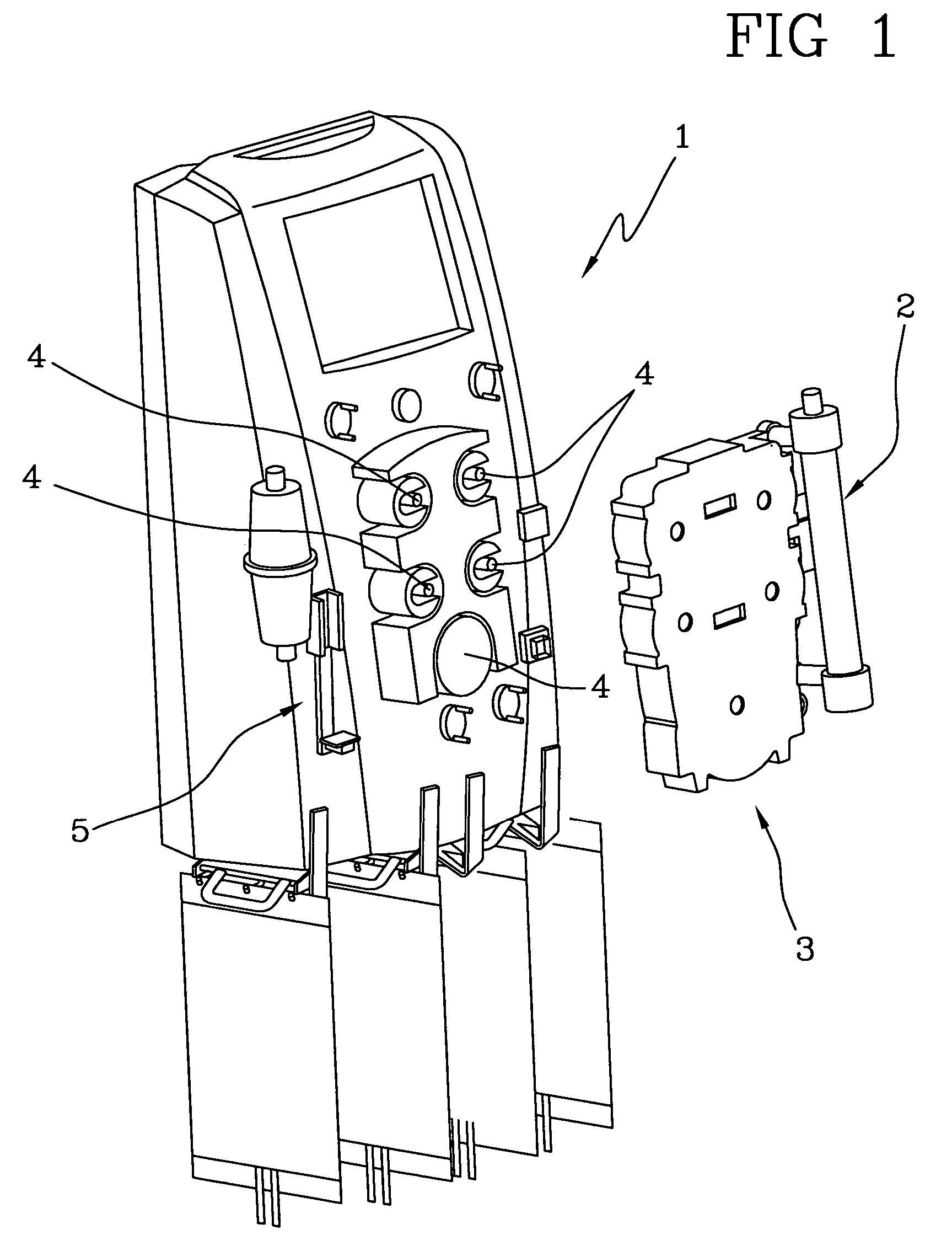
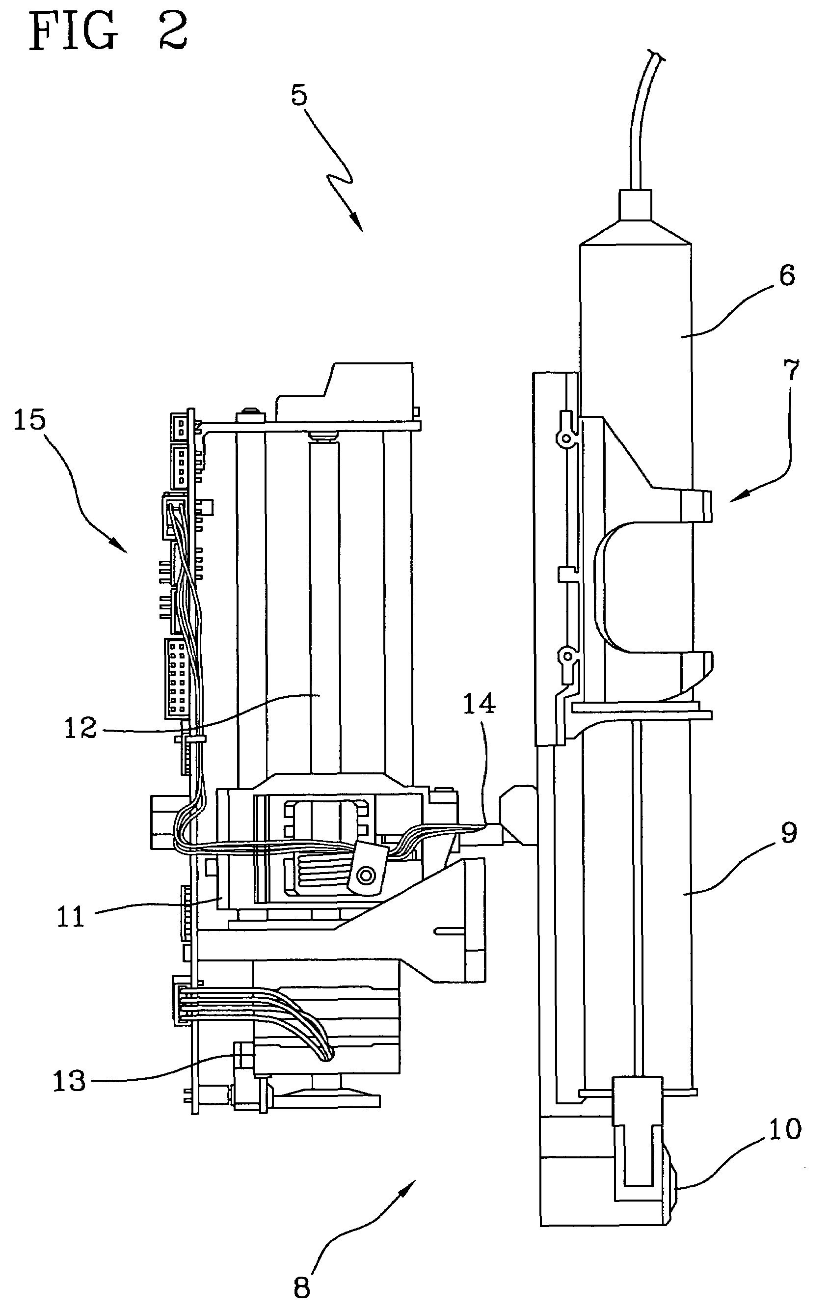
[0035]1 Machine for extracorporeal blood treatment[0036]2 Blood treatment device[0037]3 Fluid distribution circuit[0038]4 Tube deformation-type pumps (peristaltic)[0039]5 Infusion device[0040]6 Syringe[0041]7 Syringe holder[0042]8 Actuator of the infusion device[0043]9 Syringe plunger[0044]10 Actuator pusher[0045]11 Actuator truck[0046]12 Endless screw translator of actuator[0047]13 Actuator motor[0048]14 Force sensor[0049]15 Actuator controller

[0050]1 denotes in its entirety a machine for extracorporeal blood treatment which, in the specific case, is a dialysis machine for treatment of renal insufficiency which can perform, selectively, the following treatments: hemodialysis, pure ultrafiltration, hemofiltration, hemodiafiltration, therapeutic plasma exchange. The machine of FIG. 1 is especially suitable for intensive treatment of acute kidney failure.

[0051]A blood treatment device 2 (dialyzer filter) is associated operatively with the dialysis machine 1; al...


PUM


Abstract

An infusion device comprises a pusher for a plunger of a syringe containing a liquid to be infused. A load cell measures the push force. An encoder associated to a motor commanding the pusher measures the displacement of the pusher. A controller signals an alarm when the ratio between the variation of the push force and the displacement exceeds a predetermined threshold. The device, which serves for infusing an anticoagulant into an extracorporeal blood circuit in a dialysis apparatus, is able to signal an onset of an anomalous situation of lack of infusion in good time.

Description

CROSS-REFERENCE TO RELATED APPLICATIONS[0001]This application claims the benefit of priority of U.S. provisional application no. 60 / 522,442, filed Oct. 1, 2004, and Italian patent application no. MO2004A000085, filed Apr. 20, 2004, both of which are incorporated herein by reference in their entirety.BACKGROUND OF THE INVENTION[0002]The invention relates to an infusion device for medical fluids, in particular for an extracorporeal blood circuit.[0003]Specifically, though not exclusively, the invention can be usefully applied for infusing an anticoagulant in an extracorporeal circuit operatively associated with a machine for extracorporeal blood treatment.[0004]Extracorporeal treatments usually include a removal of blood from the patient, external treatment thereof away from the human body, followed by its return, after treatment, into circulation.[0005]Extracorporeal blood is made to circulate through a circuit comprising, in general, an arterial line, or blood removal line, which ta...

Claims


Application Information

Patent Timeline
Patent Type & Authority Patents(United States)
IPC IPC(8): A61M37/00A61M1/00F04B49/00B67D5/30A61M31/00G01F11/00B65D88/54F04B17/00F04B49/06B67D5/22A61M1/14A61M1/36A61M5/145A61M5/168B67D7/22B67D7/30
CPCA61M5/1456A61M5/16854A61M1/3672A61M2202/0478A61M2205/18A61M2205/332A61M2205/50A61M2205/52
Inventor TONELLI, CLAUDIOLIGABUE, ANDREACESTARI, SILVANO
Owner GAMBRO LUNDIA AB
Why Eureka
Try Eureka