Managing traffic in a multiport network node using logical ports

a network node and traffic management technology, applied in data switching networks, frequency-division multiplexes, instruments, etc., can solve problems such as more difficult tasks, less traffic, and less traffic sent by the assigned port of the vlan

Active Publication Date: 2009-04-14
WSOU INVESTMENTS LLC +1
View PDF23 Cites 52 Cited by
  • Summary
  • Abstract
  • Description
  • Claims
  • Application Information

AI Technical Summary

Benefits of technology

[0011]A technique for implementing VLANs across a service provider network involves establishing logical ports that have bindings to transport tunnels. The logical ports are then treated the same as physical ports in defining broadcast domains and forwarding traffic at particular service provider edge devices. Because the logical ports have bindings to transport tunnels, adding a particular logical port to a broadcast domain causes traffic from the respective VLAN to automatically be forwarded in the transport tunnel that is bound to the logical port. Logical ports enable a VLAN that spans an intermediate network to be established simply by adding the respective logical port to the broadcast domain of the VLAN.

Problems solved by technology

Ethernet, on the other hand, was not originally designed to provide advanced services and as a result, solutions to customer needs can be more difficult to implement in Ethernet-based networks.
While establishing broadcast domains to connect remote customers is fairly straight forward when service provider network nodes are directly connected, the task becomes more difficult when service provider edge devices are connected through an intermediate network using tunneling technologies.
In particular, the mere assigning of ports to a VLAN does not ensure that the traffic will be sent in the correct “tunnel” to the desired remote-end service provider edge device.
The difficulty of the task is further increased as the number of different customers, service provider nodes, VLANs, and tunnels grows.

Method used


Image

  • Managing traffic in a multiport network node using logical ports
  • Managing traffic in a multiport network node using logical ports
  • Managing traffic in a multiport network node using logical ports

Examples


Embodiment Construction

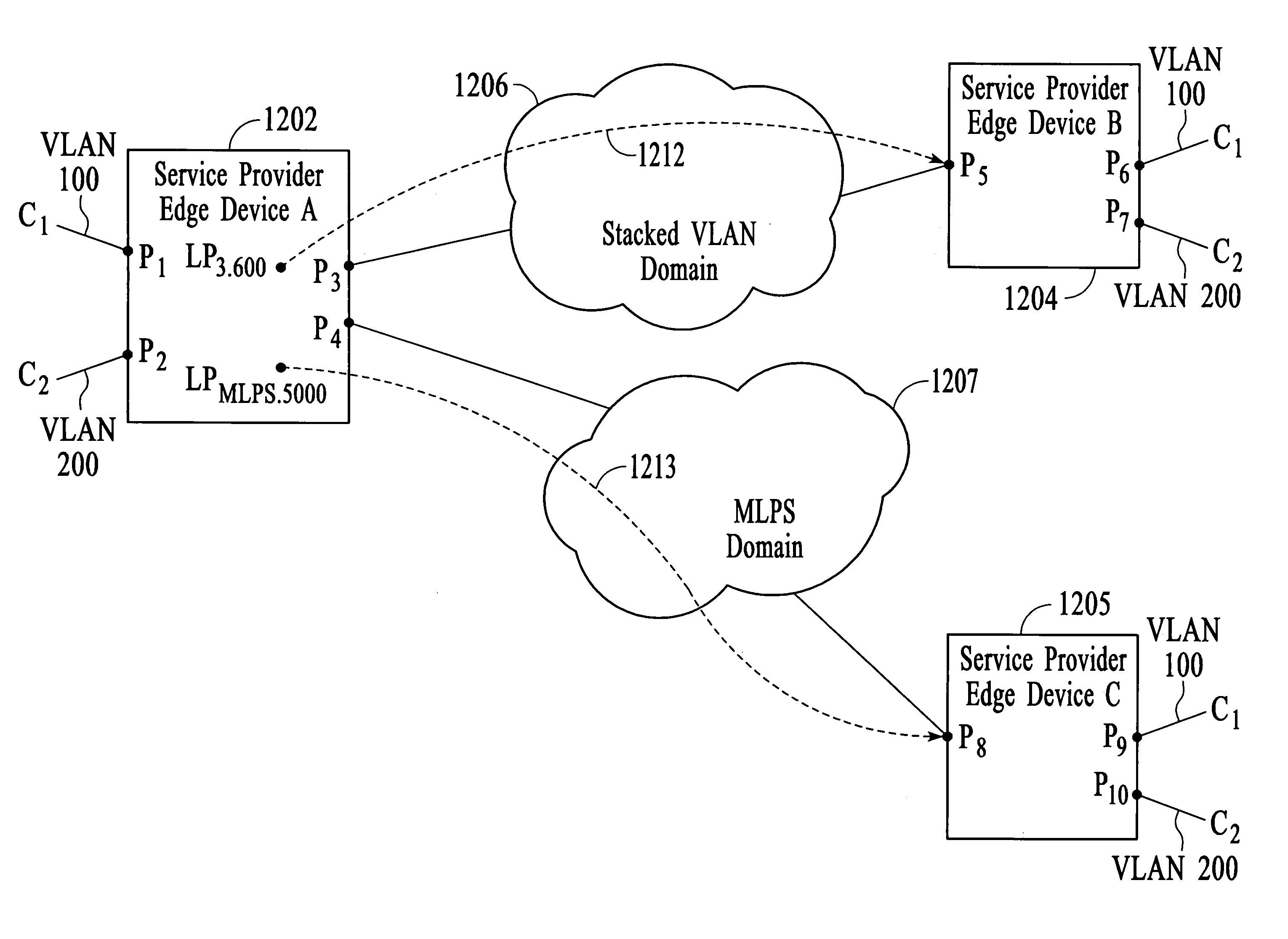
[0037]FIG. 3 depicts a network in which customer locations are connected via two service provider edge devices 302 and 304 and an intermediate network 306. In the example, customer C1 is connected to service provider edge device (SPED) A at port P1 and to SPED B at port P5. Customer C1 wants to communicate between its two locations using VLAN 100. Customer C2 is connected to SPED A at port P2 and to SPED B at port P6. Customer C2 wants to communicate between its two locations using VLAN 200. In the example of FIG. 3, the intermediate network supports “stacked VLAN tunneling” and is referred to as a “stacked VLAN domain.” In an embodiment, stacked VLAN tunneling involves encapsulating a first packet that is formatted according to the IEEE 802.1Q protocol (referred to herein as an “802.1Q packet”) into a second 802.1Q packet. The header of the second 802.1Q packet (i.e., the outer packet header) is used to forward the packet through the stacked VLAN domain and is removed at the far-en...


PUM


Abstract

A technique for implementing VLANs across a service provider network involves establishing logical ports that have bindings to transport tunnels. The logical ports are then treated the same as physical ports in defining broadcast domains at particular service provider edge devices. Logical ports can be established for Layer 2 transport tunnels that use stacked VLAN tunneling and MPLS tunneling. Establishing a logical port that uses stacked VLAN tunneling involves binding a physical port and a stacked VLAN tunnel to the logical port. Establishing a logical port that uses MPLS tunneling involves binding an MPLS tunnel to a logical port. In one embodiment, the logical port is bound to a static MPLS tunnel and in another embodiment, the logical port is bound to a dynamic MPLS tunnel and the destination IP address of the destination service provider edge device.

Description

CROSS-REFERENCE TO RELATED APPLICATION[0001]This application is entitled to the benefit of provisional Patent Application Ser. No. 60 / 385,862, filed 4 Jun. 2002.FIELD OF THE INVENTION[0002]The invention relates generally to a technique for managing traffic in a multiport network node, and more particularly, to a technique for managing traffic in a multiport network node that is connected to another network node by a tunnel, for example, a stacked virtual local area network (VLAN) tunnel or a multiprotocol label switching (MPLS) tunnel.BACKGROUND OF THE INVENTION[0003]Traditional metropolitan area communications services are based upon technologies such as asynchronous transfer mode (ATM), synchronous optical network (SONET), and Frame Relay technologies, which are optimized for voice communications services. With the increased use of the Internet as a communications medium, non-voice traffic (often referred to as data traffic) is becoming the most prevalent type of network traffic. ...

Claims


Application Information

Patent Timeline
Patent Type & Authority Patents(United States)
IPC IPC(8): H04L12/28G06F15/16G06F15/173H04L12/24H04L12/46H04L12/56
CPCH04L12/24H04L12/467H04L41/00H04L45/50
Inventor ISHWAR, PRASHANTHGAONKAR, AJAYMEHTA, APURVASUBBIAH, RAJAGOPALAN
Owner WSOU INVESTMENTS LLC
Why Eureka
Try Eureka