Laser annealing apparatus

a laser annealing and annealing technology, applied in the field of laser annealing apparatus, can solve the problems of poor flexibility, inability to work efficiently, damage to optical fibers, etc., and achieve the effect of high-quality working performan

Inactive Publication Date: 2009-04-14
LASERFRONT TECH
View PDF4 Cites 23 Cited by
  • Summary
  • Abstract
  • Description
  • Claims
  • Application Information

AI Technical Summary

Benefits of technology

[0016]It is an object of the present invention to provide a compact laser annealing apparatus which makes it possible to transmit laser power by means of a slender optical fiber even in cases in which a green laser with a high peak power such as the second harmonic of an Nd:YAG laser having a Q switching action or the like is used as a heating light source, and which therefore allows high-quality working to be carried out without any need for a laser amplifier or a high frequency generating apparatus.
[0020]It is desirable that the intensity of the laser beams that are incident on the optical fibers be varied in units of single fibers or a plurality of fibers by varying the reflectivity of the partially reflective mirrors.
[0024]In the present invention, laser power transmission can be accomplished without damaging the end surfaces of slender optical fibers even in cases in which a green laser with a high peak power such as the second harmonic of an Nd:YAG laser having a Q switching action is used as the heating light source in the crystallization annealing process of a low-temperature poly-silicon TFT. Accordingly, a laser annealing apparatus having a high-quality working performance which does not require a laser amplifier or a high frequency generating apparatus can be realized, and the operating stage of the laser annealing apparatus can be made compact.

Problems solved by technology

Furthermore, if the alignment of the optical system including the laser oscillator 201 is taken into account, the scanning of the linear beam formation optical system 202 lacks stability, is poor in terms of flexibility, and is impractical.
However, as the output of the laser oscillator is increased, there is a danger of damage to the optical fibers because of the damage limit of the optical fibers with respect to the laser power density, and the use of small-diameter optical fibers becomes difficult.
However, the actual manufacture of such optical systems is extremely difficult.
Furthermore, in the case of laser oscillators operated by Q switching, arbitrary control of the laser pulse waveform and spatial intensity distribution is difficult, and conditions that are optimal for working therefore cannot always be obtained.

Method used


Image

  • Laser annealing apparatus
  • Laser annealing apparatus
  • Laser annealing apparatus

Examples


first embodiment

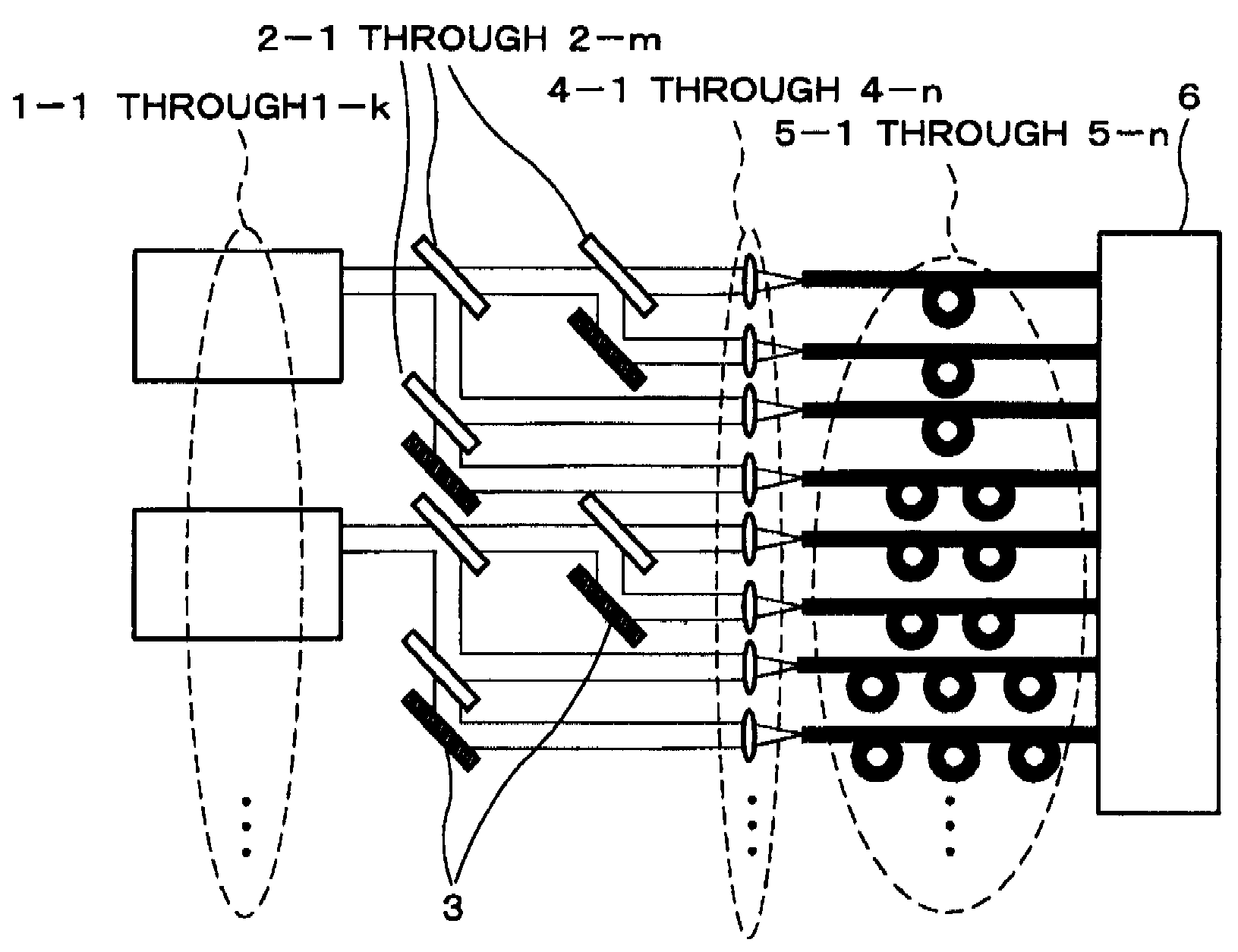
[0036]Below, embodiments of the present invention will be described in concrete terms with reference to the attached figures. FIG. 5 is a schematic diagram showing the construction of a laser annealing apparatus according to the present invention. First, k (k is a natural number) laser oscillators 1-1 through 1-k which operate by Q switching are arranged side by side, and m (m is a natural number>k) partially reflective mirrors 2-1 through 2-m which have an arbitrary reflectivity and in which dielectric multi-layer films are formed on the respective front surfaces, as well as a plurality of totally reflective mirrors 3, are disposed in front (in optical terms) of the k laser beams that have a high peak power and are emitted from the k laser oscillators 1-1 through 1-k. In the present embodiment, the pulse oscillation timing of the laser beams emitted from the k laser oscillators 1-1 through 1-k is all synchronized, and the m partially reflective mirrors 2-1 through 2-m all have the ...

third embodiment

[0069]In the example described above, the power of the transmitted laser beams is controlled by varying the number of optical fibers of respective diameters. However, if the power is within the range restricted by the damage threshold value of the end surfaces of the optical fibers, it would also be possible to adjust the power of the transmitted laser beams by employing a spit ratio for the m (m is a natural number>k) partially reflective mirrors 2-1 through 2-m, as in the third embodiment described above.

[0070]Next, a fifth embodiment of the present invention will be described. In the first embodiment described above, the arrangement direction of the emission ends of the n optical fibers 5-1 through 5-n coincided with the long direction of the beam shape of the linear beam 14 emitted from the short-side focusing cylindrical lens 13. In the present embodiment, on the other hand, the emission ends of the n optical fibers 5-1 through 5-n are disposed so that these emission ends are s...

sixth embodiment

[0074]Next, the present invention will be described. FIG. 10 is a schematic diagram showing one example of the arrangement of the optical fibers in this embodiment. In the present embodiment, as is shown in FIG. 10, the emission ends of the n optical fibers 5-1 through 5-n are shifted in units of single fibers or a plurality of fibers in the direction perpendicular to the long direction of the beam shape of the linear beam 14 from the short-side focusing cylindrical lens 13, and the core diameters of the n optical fibers 5-1 through 5-n are also varied in units of single fibers or a plurality of fibers.

[0075]As is shown in FIG. 10, three sets of optical fibers having different core diameters and fiber lengths are provided. In the slender optical fiber set 101, the respective core diameters R101 are the shortest, and the respective fiber lengths L101 are also the shortest.

[0076]An intermediate optical fiber set 102 having core diameters R102 is linearly disposed so that this set is s...


PUM

PropertyMeasurementUnit
weightaaaaaaaaaa
wavelengthaaaaaaaaaa
propagation delay timeaaaaaaaaaa

Abstract

A laser annealing apparatus comprises a laser oscillator having a Q switching action, one or a plurality of partially reflective mirrors for split a laser beam emitted from the laser oscillator into a plurality of laser beams, a plurality of optical fibers which respectively transmit the plurality of laser beams split by the partially reflective mirrors, and whose respective emission ends are arranged linearly in one direction, a first optical system for synthesizing and homogenizing the plurality of laser beams emitted from the optical fibers, and a second optical system for focusing the laser beam emitted from the first optical system on the work piece surface as a rectangular laser beam whose beam shape is long in the lateral direction and short in the longitudinal direction. As a result, laser power transmission by means of slender optical fibers is possible even in cases in which a green laser such as the second harmonic of an Nd:YAG laser having a Q switching action or the like is used as a heating light source. Accordingly, a compact laser annealing apparatus that has a high-quality working performance and does not require a laser amplifier or high-frequency generating apparatus can be obtained.

Description

BACKGROUND OF THE INVENTION[0001]1. Field of the Invention[0002]The present invention relates to a laser annealing apparatus, and more particularly to a laser annealing apparatus which is suitable for use in crystallization annealing processes of low-temperature poly-silicon TFT (thin film transistors) and the like.[0003]2. Description of the Related Art[0004]In the crystallization annealing processes of low-temperature poly-silicon TFT, XeCl lasers are widely used as heating light sources. Recently, the fact that green lasers having a high peak power, as represented by the second harmonic of Nd:YAG (yttrium aluminum garnet) lasers having a Q switching action, can be used as heating light sources has attracted great attention because of the ability of such lasers to achieve greater crystal growth at a lower running cost. In annealing processes using green lasers having a high peak power, a system in which a laser beam is formed as a linear beam and directed onto the substrate is mos...

Claims


Application Information

Patent Timeline
Patent Type & Authority Patents(United States)
IPC IPC(8): G02B6/04H01L21/268
CPCG02B6/4296G02B27/0911G02B27/0927G02B27/0994H01L21/268H01S3/005B23K26/0604B23K26/0626B23K26/0732
Inventor MORITA, LEGAL REPRESENTATIVE, KEIKOMORITA, HIROYUKI
Owner LASERFRONT TECH
Why Eureka
Try Eureka