Hydrant shoe with backflow prevention assembly

a backflow prevention and fire hydrant technology, applied in the field of fire hydrant security, can solve the problems of increasing the risk of fire damage, unauthorized use or contamination of fire hydrants, and public water safety, and achieve the effect of controlling communication

Active Publication Date: 2009-04-21
MUELLER INT LLC
View PDF59 Cites 14 Cited by
  • Summary
  • Abstract
  • Description
  • Claims
  • Application Information

AI Technical Summary

Benefits of technology

[0020]In preferred form, a fire hydrant system relating to protection of a water supply from contamination is described herein. The fire hydrant system includes a barrel, a nozzle, a hydrant valve, a valve actuator, and a hydrant shoe. The barrel is adapted to communicate at least indirectly with a water supply. The nozzle is adapted to extend from the barrel. The hydrant valve is adapted to controllably regulate communication between the barrel and the water supply. The valve actuator is adapted to allow actuation of the hydrant valve. The hydrant shoe is in communication with the water supply, and comprises a backflow prevention assembly. The backflow prevention assembly is adapted to allow water to flow from the water supply through the hydrant shoe into the barrel at an open position of the backflow prevention assembly, and is further adapted to prevent media from entering the water supply via the barrel when the backflow prevention assembly is in a closed position.
[0021]The hydrant shoe preferably includes a body defining a hollow cavity. The backflow prevention assembly is preferably positioned within the hollow cavity, and can comprise a disc and seat. The disc is adapted to rotate between an open and closed position depending on water flow or media pressure. Should an unauthorized user attempt to deliver toxins, contaminants, or other materials into the water supply at a pressure that exceeds the water line pressure from the water supply the disc will be forced onto seat, creating a sealing arrangement that can prevent toxins or other materials from entering into the main water supply.

Problems solved by technology

Unfortunately, this accessibility can expose the fire hydrants to unauthorized use or contamination.
For example, the hydrant can be opened by an unauthorized person in an attempt to contaminate the public water supply by introducing toxins or other dangerous materials into the hydrant, and thus into the water supply.
Unauthorized hydrant use can also result in low water pressure throughout the neighborhood or community where the hydrant is located, which could increase the risk of fire damage, due to inadequate water pressure.
Clearly, public water safety is an issue that deserves awareness and protection.
Although, the pentagon-shape is considered “non-standard” and requires a special wrench, it may also be easily operated with different tools, such as a pipe wrench.
Unfortunately, each requires different tools to operate the fire hydrant, and cannot be operated by a standard tool, such as a conventional wrench.
Thus, if fire fighters do not happen to have the correct tool with them, they cannot access the water supply.
As a result, while these solutions attempt to solve problems with preventing access to the water supply, they actually create more problems, and may prevent the desired or necessary access to the water supply, particularly in an emergency.
Unfortunately, neither of these approaches is satisfactory.
In some instances a special type of hydrant is required, so that it is not possible to apply the locking device to existing hydrants.
In other instances, the locking device is designed for the standard hydrant but, because of its complexity, is difficult to operate.
In addition, damage to an operating nut and nozzle, or jamming of the protective devices, can be a problem.
For instance, vandals can strike the hydrant with a sledgehammer, or other object, to deliver a considerable force, causing the protective device to ultimately break or prevent removal of same during an emergency.
Regrettably, the positioning of these backflow prevention devices permit access from the open end of nozzle, which could result in damage, breakage, or even removal of the backflow prevention device.
Furthermore, these arrangements are also complex and require precise machining.

Method used


Image

  • Hydrant shoe with backflow prevention assembly
  • Hydrant shoe with backflow prevention assembly
  • Hydrant shoe with backflow prevention assembly

Examples


Embodiment Construction

[0033]To facilitate an understanding of the principles and features of the invention, it is explained hereinafter with reference to its implementation in an illustrative embodiment. In particular, the invention is described in the context of being a backflow prevention assembly for a fire hydrant, preferably a dry-barrel fire hydrant.

[0034]Referring now in detail to the drawing figures, wherein like reference numerals represent like parts throughout the several views, a hydrant shoe having a backflow prevention assembly is in fluid communication with a conventional fire hydrant.

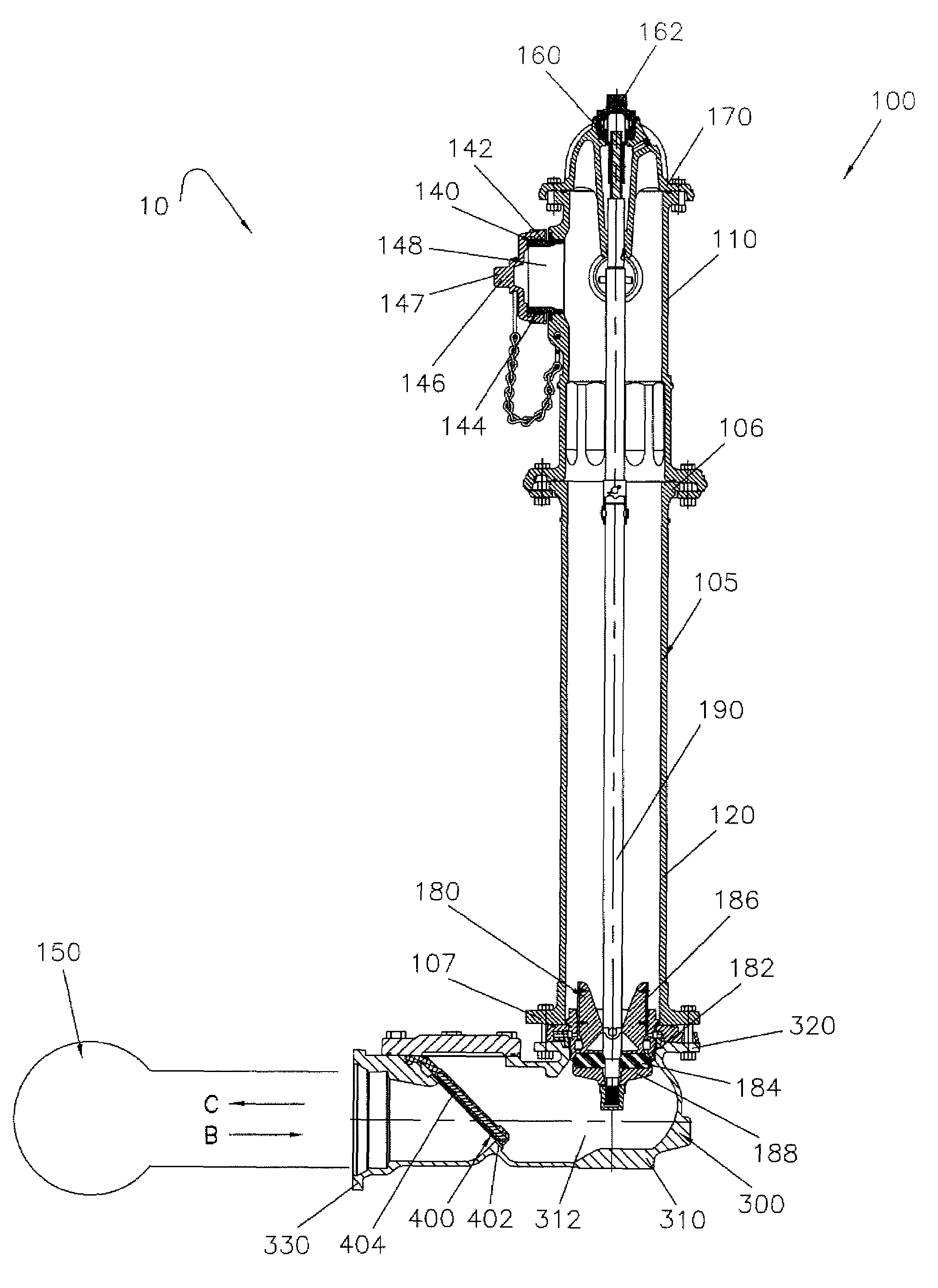
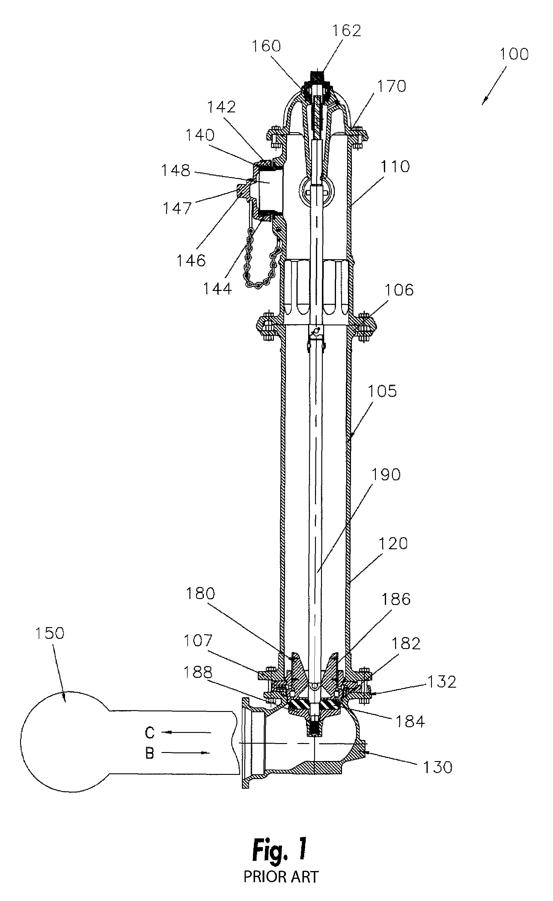
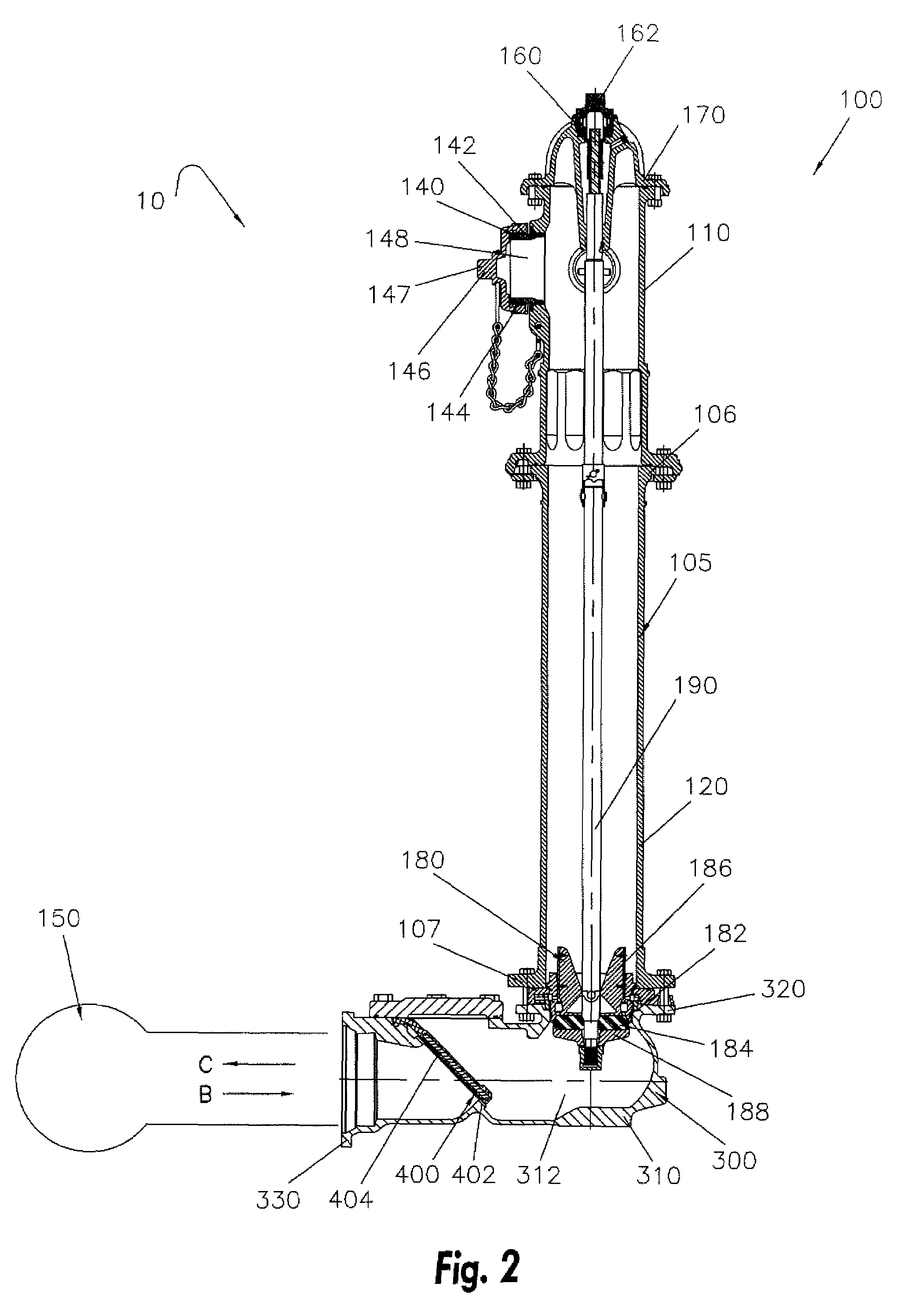
[0035]FIG. 2 illustrates a cross-sectional view of a fire hydrant that is connected to a hydrant shoe. FIG. 3 illustrates a side view of the hydrant shoe. FIG. 4 illustrates a top view of the hydrant shoe, while FIGS. 5-6 illustrate side, cross-sectional views of the hydrant shoe across the line A-A of FIG. 4.

[0036]More specifically, FIG. 2 illustrates a fire hydrant system 10, which includes generally simila...


PUM


Abstract

A fire hydrant system relating to protection of a water supply from contamination. The fire hydrant system includes a barrel adapted to communicate at least indirectly with a water supply; a nozzle extending from the barrel; a hydrant valve adapted to controllably regulate communication between the barrel and the water supply; a valve actuator adapted to allow actuation of the hydrant valve; a nozzle cap adapted to at least close off the nozzle opening; and a hydrant shoe in communication with the water supply, the hydrant shoe comprising a backflow prevention assembly, wherein water can flow from the water supply through the hydrant shoe into the barrel at an open position of the backflow prevention assembly disc, and wherein media cannot enter the water supply via the barrel when the backflow prevention assembly disc is in a closed position.

Description

CROSS REFERENCE TO RELATED APPLICATION[0001]This application claims benefit, under 35 U.S.C. § 119(e), of U.S. Provisional Application Ser. No. 60 / 815,394, filed 21 Jun. 2006, the entire contents and substance of which are hereby incorporated by reference.BACKGROUND[0002]1. Field of the Invention[0003]The present invention relates to hydrant security and, more particularly, to a backflow prevention assembly for a fire hydrant for preventing contamination of a municipal water supply.[0004]2. Description of Related Art[0005]Conventional fire hydrants provide a convenient and familiar water outlet, and are typically located throughout communities for fighting fires. Fire hydrants are in fluid communication with water lines, or a municipal water supply, such that they have enough water pressure to rise through the hydrant body and spray outwardly when a valve of the fire hydrant is open. Hydrants are typically located in public areas making them able to be quickly located, and easily ac...

Claims


Application Information

Patent Timeline
Patent Type & Authority Patents(United States)
IPC IPC(8): E03B9/02
CPCE03B9/16Y10T137/7903Y10T137/88054Y10T137/79Y10T137/5491
Inventor GERMAN, MIKHAILFLEURY, LEO W.CLARK, KEN
Owner MUELLER INT LLC
Why Eureka
Try Eureka