Multiple dart drop circulating tool

a technology of circulating tools and darts, which is applied in the direction of fluid removal, borehole/well accessories, construction, etc., can solve the problems of increasing well service costs, multiple opportunities for operator errors, and difficulty for operators or well service providers to accurately predict the amount of fluid

Active Publication Date: 2009-04-21
BAKER HUGHES HLDG LLC
View PDF29 Cites 29 Cited by
  • Summary
  • Abstract
  • Description
  • Claims
  • Application Information

AI Technical Summary

Benefits of technology

[0012]The object of the present disclosure is to provide a downhole tool and method to divert fluid flow out of a work string to an annulus. In one embodiment an apparatus for diverting fluid flow out of a working string is disclosed comprising a housing having an internal bore, an upper end, and a lower end wherein the housing has at least one exterior port. The apparatus includes a circulating sleeve having at least one exterior port positioned within the internal bore of the housing. The circulating sleeve is adapted to sealingly slide within the internal bore from an initial position to at least a second position. In the initial position, the circulating sleeve prevents fluid flow from the internal bore to at least one exterior port of the housing. Likewise, when the circulating sleeve is in the initial position, the housing prevents fluid flow through the at least one exterior port of the circulating sleeve. In the second position, the at least one exterior port is aligned with the at least one exterior port of the housing allowing fluid flow to the annulus.
[0019]One embodiment of the present invention may be used to circulate fluid into the annulus surrounding the work string at a particular location. As discussed above, drilling mud may be entering into a porous well formation instead of properly circulating the drill cuttings to the surface. The present invention may reduce the time required to inject a sealing agent the work string, circulate the sealing agent into the annulus, and return the work string to normal flow. The present invention may also reduce circulating time and increase hole cleaning efficiency in upper annuli when used in connection with a tapered work string. The present invention could be in various other applications, such as to allow increased velocity while displacing mud to clear brine fluids, as would be appreciated by one of ordinary skill in the art having the benefit of this disclosure.
[0021]The method may include deforming the dart caught within the seat of the tool, wherein the work string does not need to be disconnected a second time to deform the dart. The method may include reducing the fluid pressure above the dart to move the sleeve to a third position, wherein in the third position the sleeve prevents communication between the central bore of the tool and the exterior fluid port of the tool. The method may further include increasing the fluid pressure above the seated dart to move the sleeve to a fourth position, in the fourth position the sleeve prevents communication between the central bore of the tool and the exterior fluid port of the tool. The method may further include increasing the fluid pressure above the dart to a predetermined pressure causing the dart to deform and pass through the seat of the tool. The method may include returning the sleeve to its initial position and catching the deformed dart with a cage housing located below the seat. The method may further include retaining the deformed dart within the cage housing. The method may further include diverting fluid flow out of the work string a second time by inserting a second dart into the work string.

Problems solved by technology

For example, the drilling mud may be entering into a porous well formation instead of properly circulating the drill cuttings to the surface.
This process causes increases in well services costs as well as providing multiple opportunities for operator error.
The use of a plastic ball may make it difficult for operators or well service providers to accurately predict the amount of fluid pressure required to pass the ball past the shoulder within the device.
This may further make it difficult to predict the fluid pressure necessary to pass the plastic ball past the shoulder.

Method used


Image

  • Multiple dart drop circulating tool
  • Multiple dart drop circulating tool
  • Multiple dart drop circulating tool

Examples


Embodiment Construction

[0033]Illustrative embodiments of the invention are described below as they might be employed in an apparatus of method of diverting fluid flow out of a work string. In the interest of clarity, not all features of an actual implementation are described in this specification. It will of course be appreciated that in the development of any such actual embodiment, numerous implementation-specific decisions must be made to achieve the developers' specific goals, such as compliance with system-related and business-related constraints, which will vary from one implementation to another. Moreover, it will be appreciated that such a development effort might be complex and time-consuming, but would nevertheless be a routine undertaking for those of ordinary skill in the art having the benefit of this disclosure.

[0034]Further aspects and advantages of the various embodiments of the invention will become apparent from consideration of the following description and drawings.

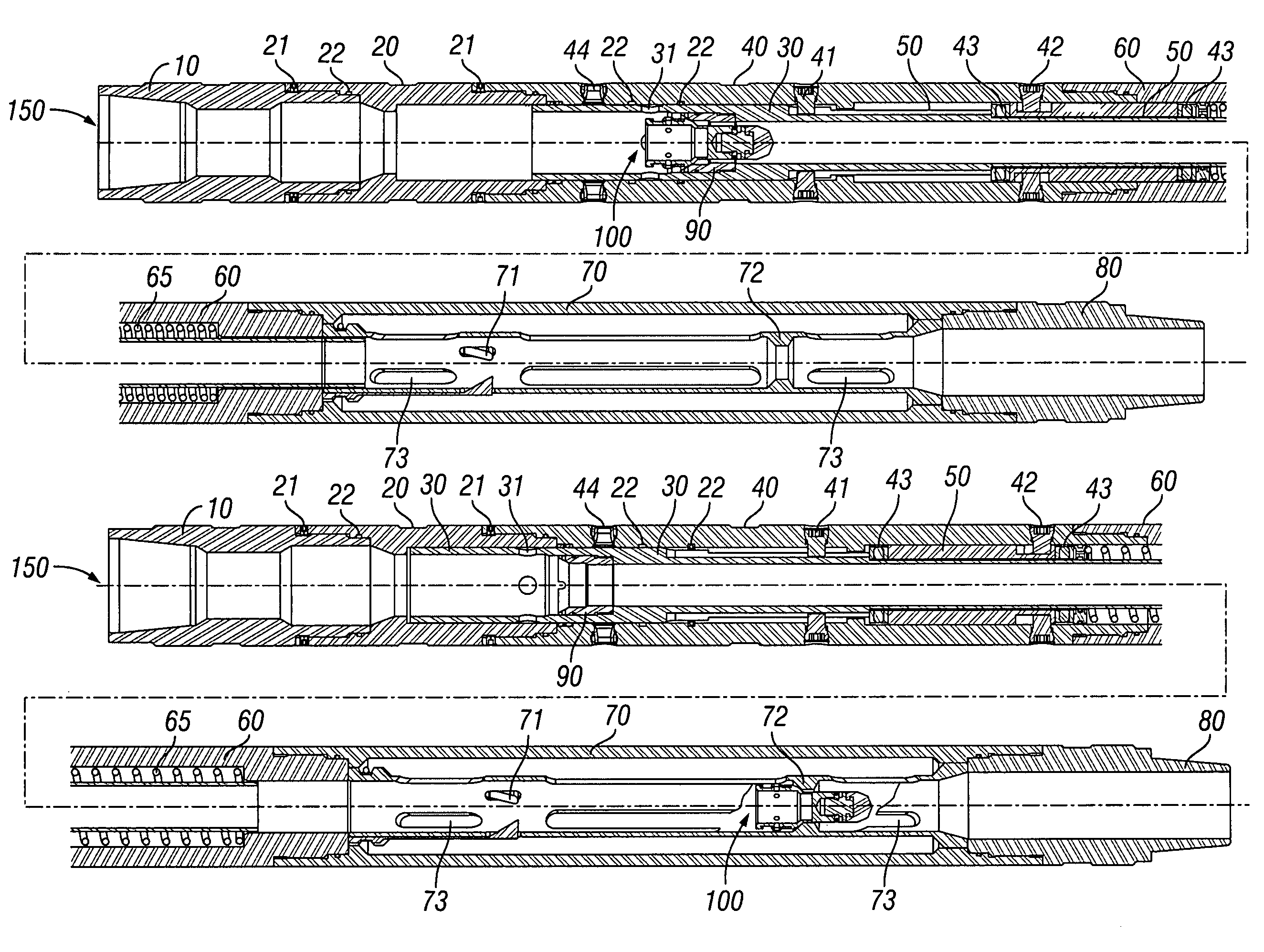
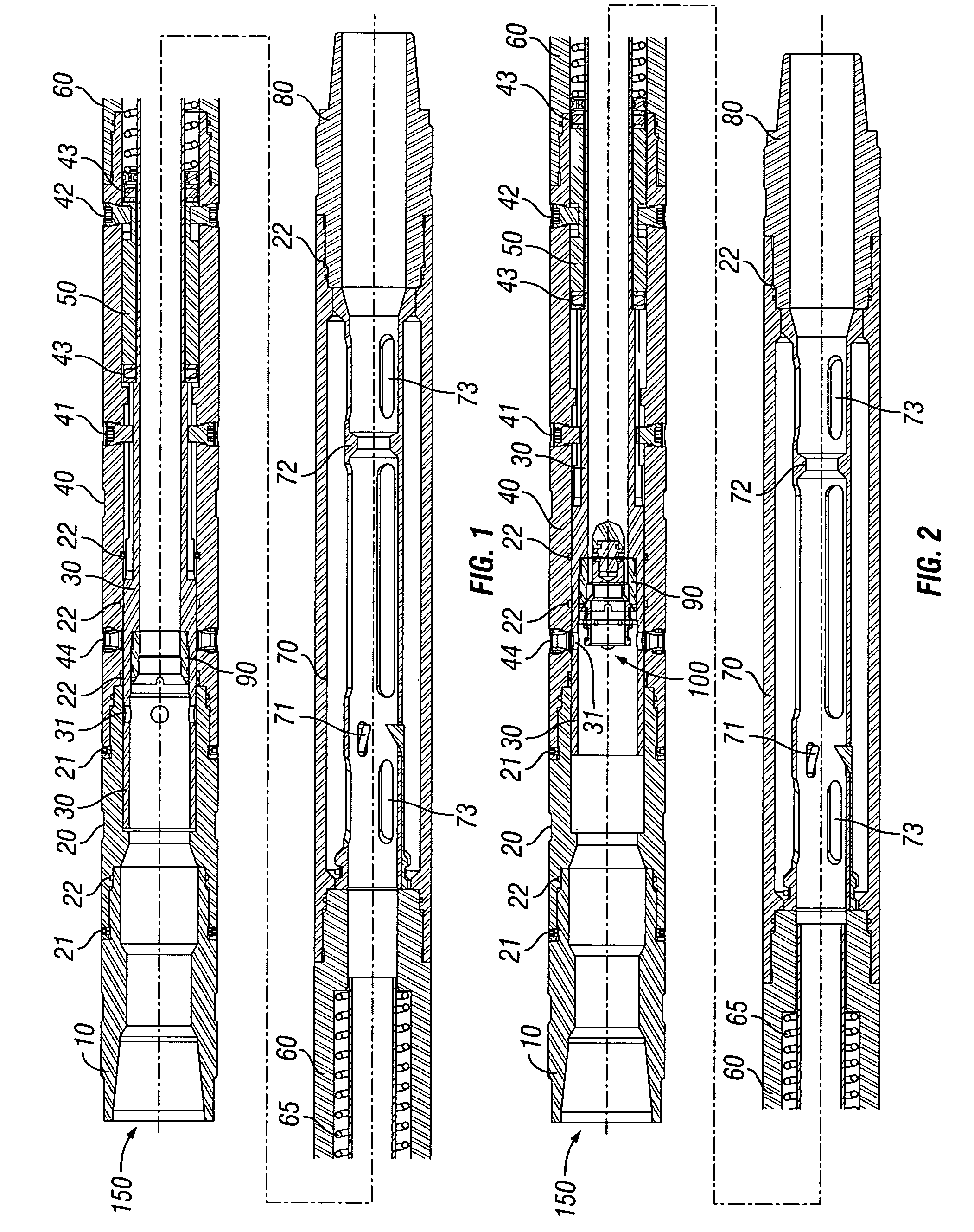
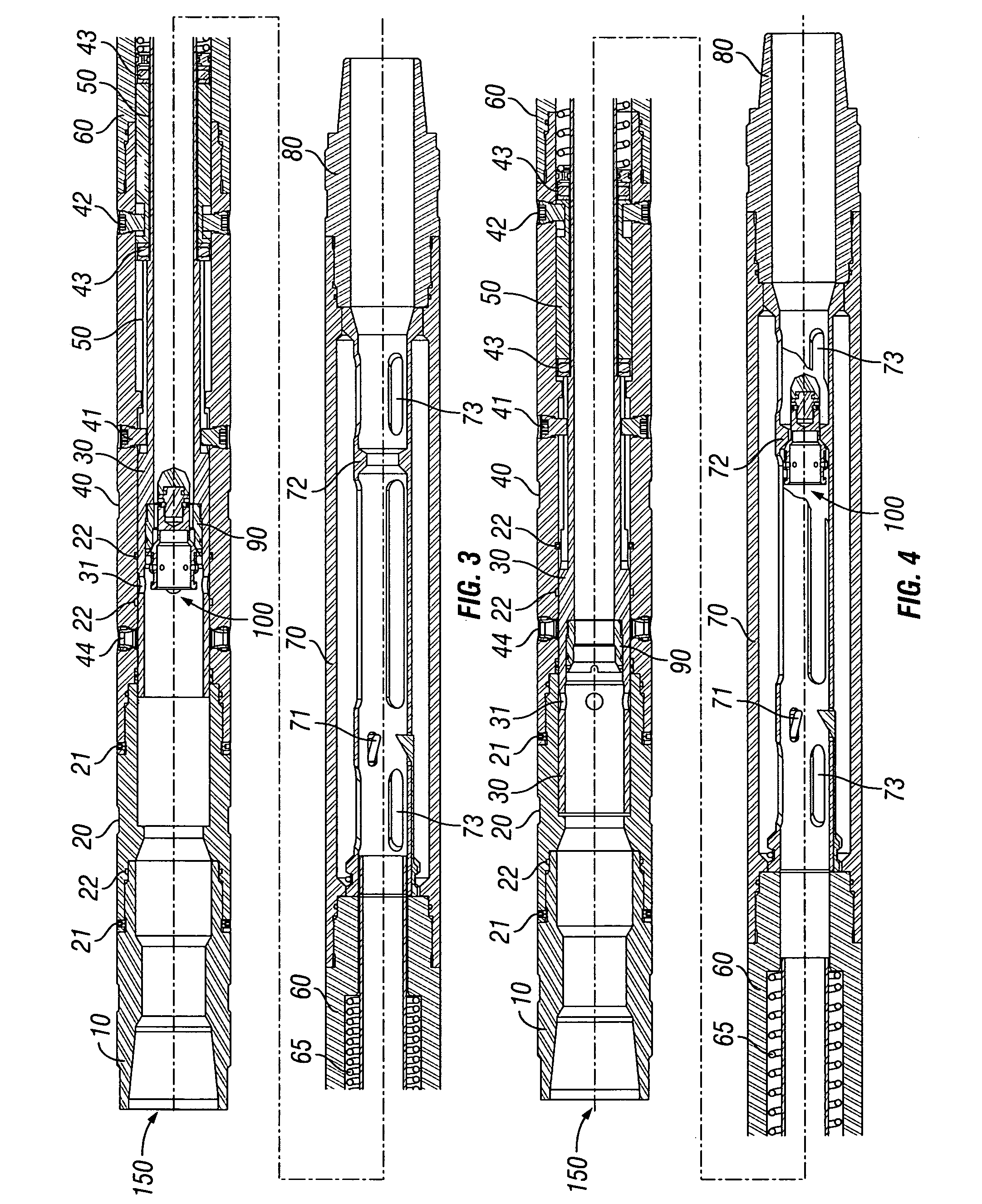
[0035]FIG. 1 shows o...


PUM


Abstract

A downhole device used to divert fluid flow out of a work string. The downhole device may be located at any point along a work string at which it may be necessary to divert the fluid flow to the annulus. The downhole device may be activated and deactivated by inserting a single deformable dart into the work string. The device catches the dart blocking fluid flow through the work string. Increased fluid pressure activates the device, which diverts the fluid flow out of the work string into the annulus. A locating sleeve with a continuous j-track allows the device to be retained in activated position. The dart is adapted to deform under a predetermined amount of fluid pressure allowing the dart past the device and returning fluid flow through the work string. The downhole device may be activated multiple times without removing the downhole device from the wellbore.

Description

BACKGROUND OF THE INVENTION[0001]1. Field of the Invention[0002]The present invention relates generally to a downhole device that may be used to divert fluid out of a work string and into the annulus between the work string and the tubing or casing. The downhole device may be located at any point along a work string at which it may be necessary to divert the fluid flow to the annulus. The downhole device may be activated and deactivate inserting a single dart into the work string. The device catches the dart, which blocks the fluid flow through the work string. The increased fluid pressure due to the blocked flow path activates the device, which diverts the fluid flow out of the work string into the annulus. The increased fluid pressure moves a circulating sleeve within the device to align fluid ports allowing fluid flow into the annulus. A locating sleeve with a continuous j-track allows the device to be retained in activated position. The dart is adapted to deform under a predeter...

Claims


Application Information

Patent Timeline
Patent Type & Authority Patents(United States)
IPC IPC(8): E21B34/14E21B23/00
CPCE21B21/103E21B23/006E21B34/14E21B2034/007E21B2200/06E21B34/142
Inventor MONDELLI, MAXIMILIANOKRIEG, GEORGEHEBERT, DAVIDROBINSON, DAVID
Owner BAKER HUGHES HLDG LLC
Why Eureka
Try Eureka