Coupling of communications signals to a power line

a technology of coupling and power line, applied in the field of communication networks, can solve the problems of limiting the efficiency of communications signal transmission over medium-voltage power lines, limiting or preventing the use of lower frequencies between communications devices, and limiting the frequency response of a communications signal coupler to roll off prematurely, etc., to achieve the effect of quick and simple installation, and improving the transmission and throughput of communications signals

Inactive Publication Date: 2009-04-21
INTERNATIONAL BROADBAND ELECTRIC COMMUNICATIONS INC
View PDF72 Cites 241 Cited by
  • Summary
  • Abstract
  • Description
  • Claims
  • Application Information

AI Technical Summary

Benefits of technology

[0007]Particular embodiments of the present invention may provide one or more technical advantages. For example, certain embodiments of the present invention may provide improved transmission and throughput of communications signals. As another example, in certain embodiments, the size and placement of the coupling device may provide for relatively quick and simple installation with little or no modifications to existing equipment. In these embodiments, such relatively quick and simple installation may allow for rapid deployment of communications coverage and / or rapid repair in the event of a localized surge or lightning strike. Certain embodiments of the present invention may provide one or more of these technical advantages at a relatively low cost.
[0008]Certain embodiments of the present invention may improve the coupling efficiency for systems utilizing MOV lightning arresters with explosive disconnect devices. These disconnect devices have been shown to limit the efficiency of communications signal transmission over medium-voltage power lines. The arrester disconnect device can cause the frequency response of a communications signal coupler to roll-off prematurely and limit or prevent the use of lower frequencies between communications devices. By bypassing this disconnect device at radio frequencies, certain embodiments of the present invention may reduce the series impedance contribution of the disconnect device and thereby reduce or eliminate this performance problem.

Problems solved by technology

These disconnect devices have been shown to limit the efficiency of communications signal transmission over medium-voltage power lines.
The arrester disconnect device can cause the frequency response of a communications signal coupler to roll-off prematurely and limit or prevent the use of lower frequencies between communications devices.

Method used


Image

  • Coupling of communications signals to a power line
  • Coupling of communications signals to a power line
  • Coupling of communications signals to a power line

Examples


Embodiment Construction

[0026]It should be understood at the outset that although example embodiments of the invention are illustrated below, the present invention may be implemented using any number of techniques, whether currently known or not. The present invention should in no way be limited to the illustrated embodiments, drawings, and techniques. Additionally, the drawings are not necessarily drawn to scale.

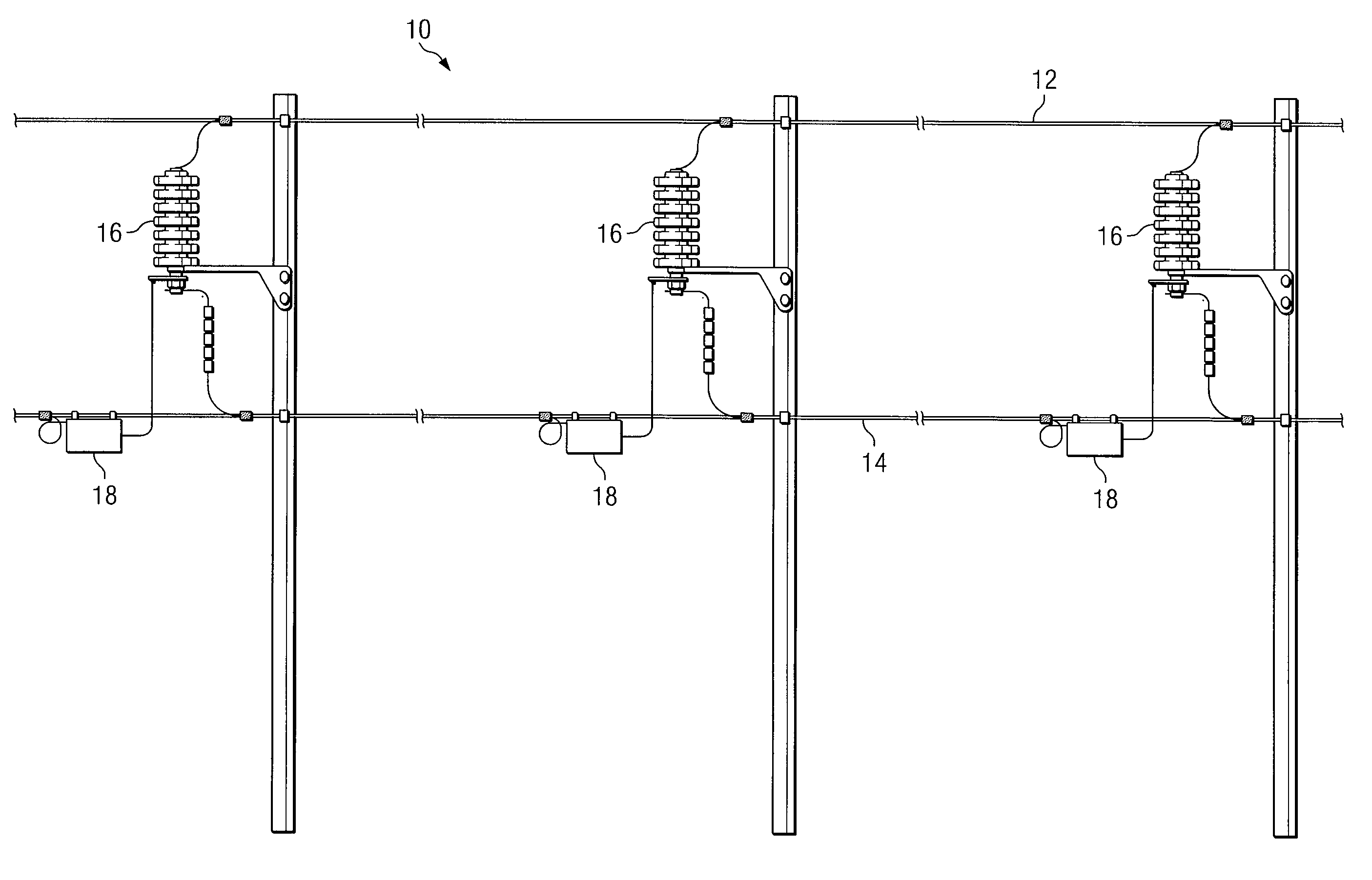
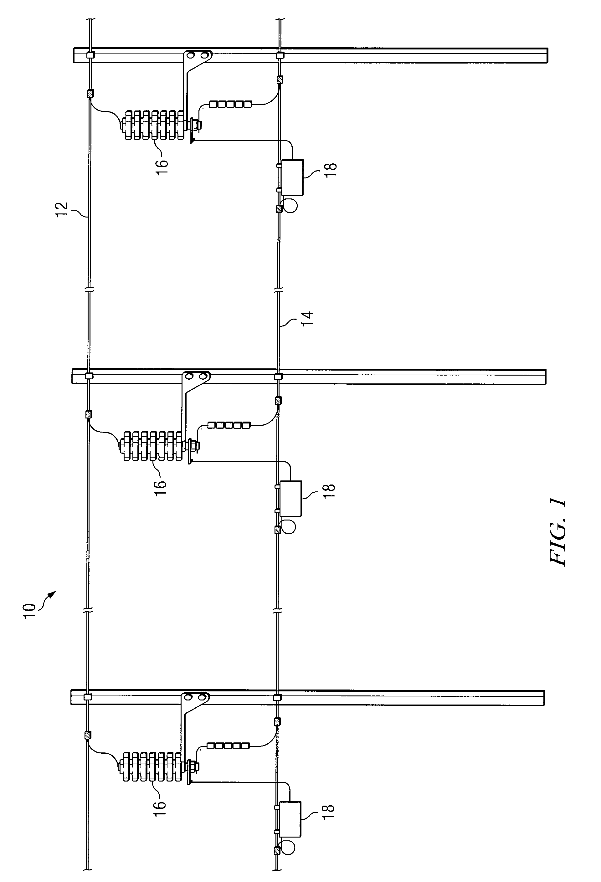
[0027]FIG. 1 illustrates a portion of an example power-line communications system, indicated generally at 10, utilizing medium-voltage power lines to carry communications signals. In certain embodiments, power-line communications system 10 may function to provide one or more customers with access to a wide area network (WAN). For example, power-line communications system 10 may function to provide one or more customers with access to data services, video services, voice-over-Internet-Protocol (VoIP), or plain-old-telephone service (POTS). As another example, the communications signals may represen...


PUM


Abstract

In one embodiment, a device for coupling communications signals onto a medium-voltage power line includes a first connector, a second connector and one or more components. The first connector is adapted to couple to a low-voltage communications line. The second connector is adapted to couple to a surge arrester. The one or more components are operable to substantially match the impedances between the surge arrester and the low-voltage communications line.

Description

RELATED APPLICATION[0001]This application claims the benefit under 35 U.S.C. § 119(e) of U.S. Provisional Application Ser. No. 60 / 700,038 filed Jul. 15, 2005.TECHNICAL FIELD[0002]This invention relates generally to communications networks and in particular to a system and method for improved coupling of communications signals to a power line.BACKGROUND[0003]Power systems utilize a variety of electrical devices and connectors to deliver electricity from a power station or generator to customers. Some power systems utilize a three-tiered approach that utilizes high-voltage power lines with voltages in the range from approximately 60 kV to 100 kV, medium-voltage power lines with voltages in the range from approximately 4 kV to 60 kV, and low-voltage power lines with voltages in the range from approximately 90V to 600V.[0004]In these three-tiered power systems, high-voltage power lines typically connect a power station or generator to a substation. The substation serves a particular are...

Claims


Application Information

Patent Timeline
Patent Type & Authority Patents(United States)
IPC IPC(8): G02B6/00
CPCH04B3/542H04B3/56H04B2203/5483
Inventor ZITTING, BRENT R.
Owner INTERNATIONAL BROADBAND ELECTRIC COMMUNICATIONS INC
Why Eureka
Try Eureka