Data control apparatus functioning as a USB mass storage device

a data control apparatus and mass storage technology, applied in the direction of memory adressing/allocation/relocation, instruments, and variable measurement arrangements, can solve the problems of large load on the measuring equipment, complicated program creation, and user burden, and achieve the effect of reducing the need for setting work as a burden on the user and facilitating data transfer

Active Publication Date: 2009-04-21
YOKOGAWA ELECTRIC CORP
View PDF5 Cites 1 Cited by
  • Summary
  • Abstract
  • Description
  • Claims
  • Application Information

AI Technical Summary

Benefits of technology

[0020]An object of the invention is to provide a data control apparatus for eliminating the need for setting work as a burden on the user and making it easy to transfer data simply just as the data control apparatus is connected to an external equipment such as a host computer.
[0028]According to the data control apparatus, the data control apparatus for performing measurement or signal generation includes the USB mass storage class control section, and the data control apparatus is identified as an external storage when the data control apparatus are connected to the external equipment by USB. Therefore, a data file can be easily exchanged between the data control apparatus and the external equipment without the need for an intricate program or setting.
[0029]The data file is transferred with usual spreadsheet software intact, for example, and general operation such as double click can be performed and therefore the operation method is extremely easy for the user.

Problems solved by technology

As a measuring equipment requiring this kind of function, for example, in a waveform measuring equipment, etc., the data amount of the waveform, etc., processed in the measuring equipment grows and the computation amount also increases with improvement of the analysis function, resulting in large load on the measuring equipment; this is a problem.
Particularly, for input / output of a data string, the data format varies from one equipment to another and program creation becomes intricate.
In addition, expert knowledge is required for program creation and a work burden is also placed on the user.
In the configuration in FIG. 8, the standard of a removal storage medium is rapidly changed or discarded and often does not match the lifetime of a data control apparatus.
Thus, it may become impossible to write or read the data stored on a storage medium as the standard is changed.
Setting the unique addresses each time is intricate work for the user.
That is, the unique addresses in the network are the resources of the network and acquiring and returning the unique addresses from and to the network administrator are intricate.

Method used


Image

  • Data control apparatus functioning as a USB mass storage device
  • Data control apparatus functioning as a USB mass storage device
  • Data control apparatus functioning as a USB mass storage device

Examples


first embodiment

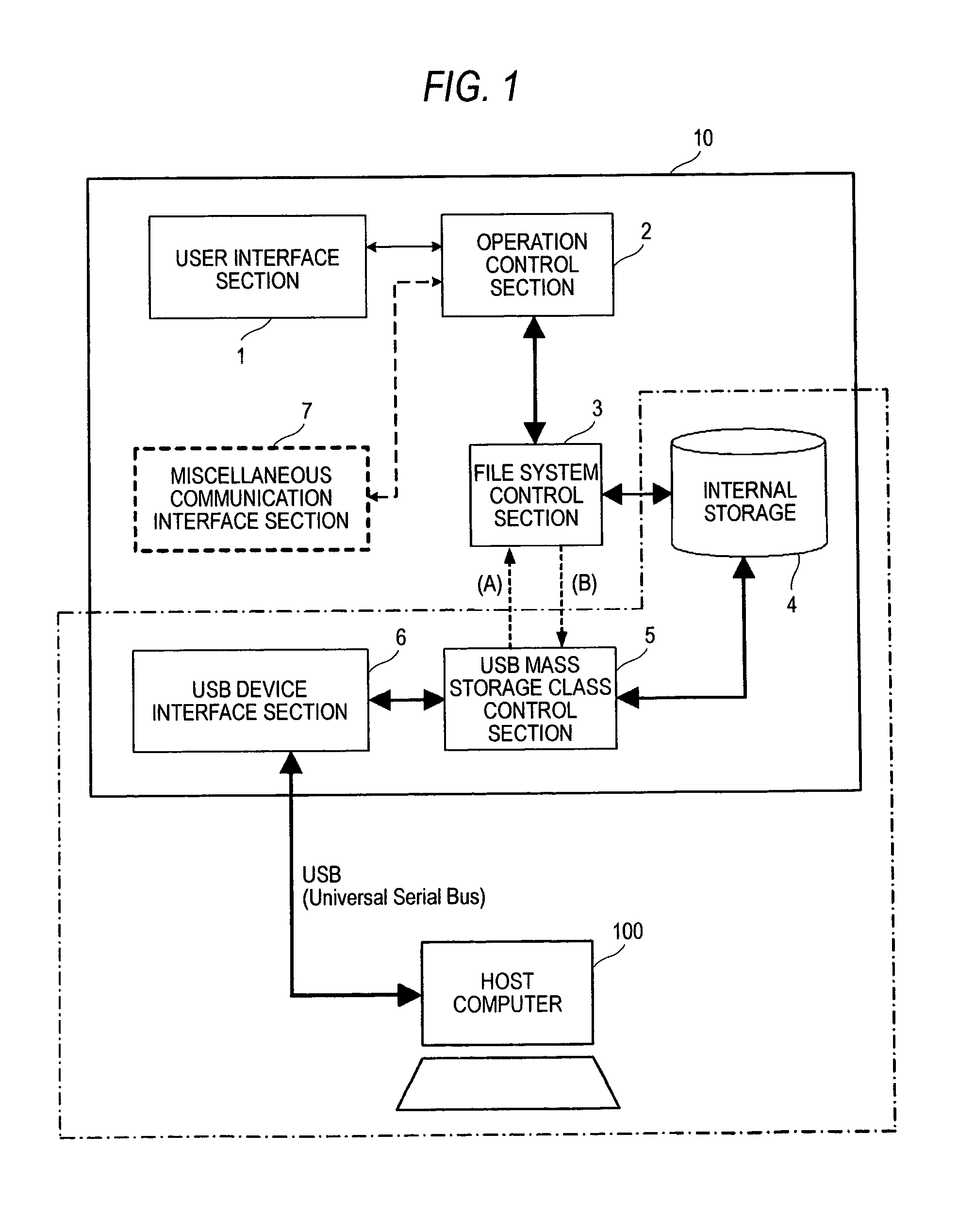
[0040]A data control apparatus according to the invention will be discussed with reference to FIG. 1. In the figure, an external equipment is a host computer 100. A user interface section 1 of a data control apparatus 10 includes a keyboard for the user to enter a command in the data control apparatus 10 and a display for displaying the result. An operation control section 2 performs signal generation or measurement and is connected to the user interface section 1 for controlling a signal land data generation function and a measurement function.

[0041]Internal storage 4 is a storage device for reading / writing in sector units, such as a hard disk or semiconductor storage, and is subjected to file management control by a file system control section 3. The file system control section 3 creates, deletes, writes, reads, etc., a file based on data stored in the internal storage 4.

[0042]A USB mass storage class control section 5 controls a protocol (USB mass storage class) for a mass storag...

second embodiment

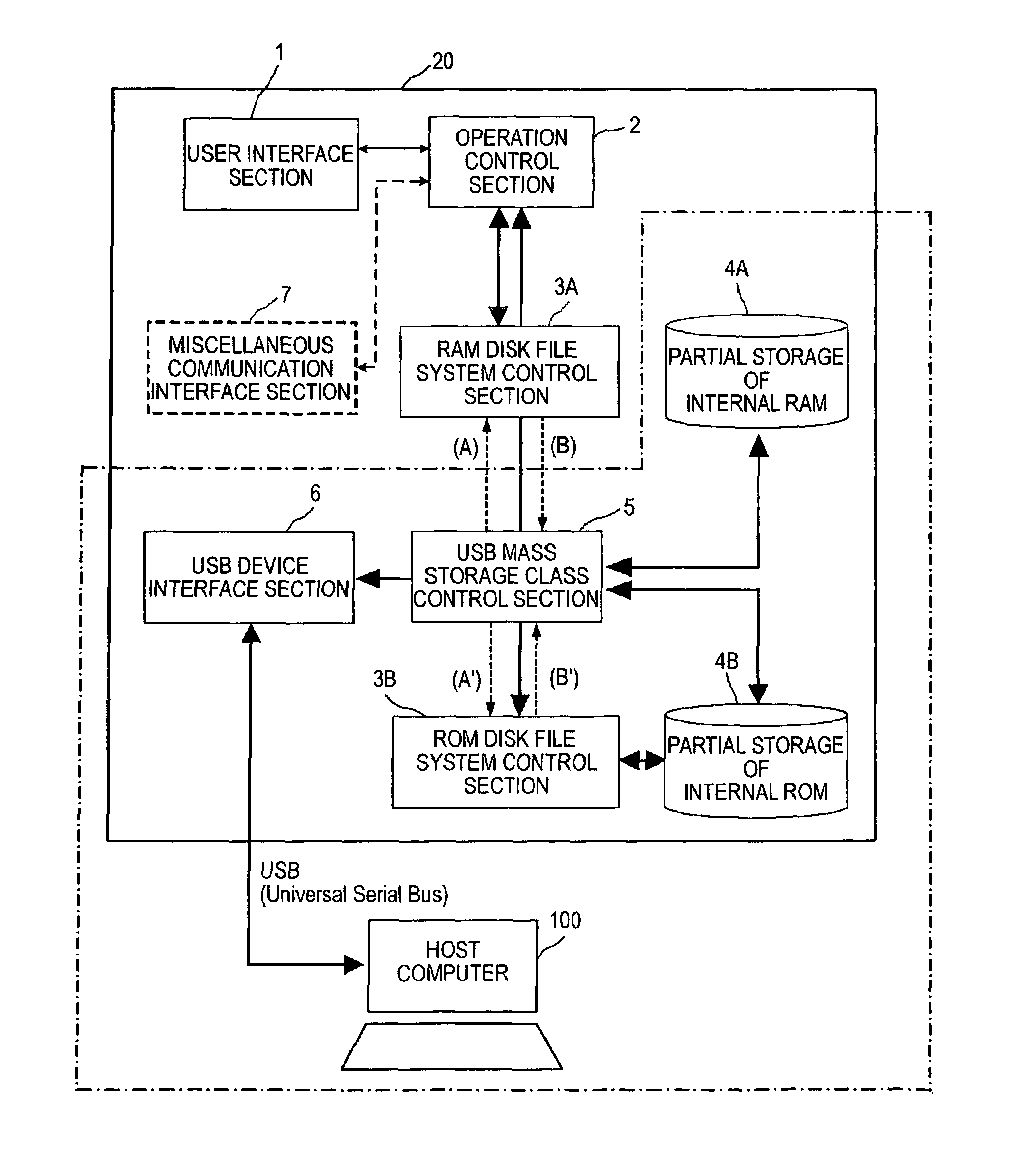
[0055]Next, a data control apparatus according to the invention will be discussed with reference to FIG. 5. In FIG. 5, a data control apparatus 20 includes partial storage of internal RAM 4A and partial storage of internal ROM 4B in place of the internal storage 4 of the data control apparatus 10 in FIG. 1, and is provided with a RAM disk file system control section 3A and a ROM disk file system control section 3B in place of the file system control section 3.

[0056]That is, FIG. 5 shows a configuration example wherein to form storage in the data control apparatus 20, a part of a RAM area and a part of a ROM area in a CPU of the data control apparatus 20 are formed as semiconductor storage by a program and the need for adding new hardware is eliminated.

[0057]The partial storage of internal RAM 4A is volatile storage and when the power is turned off, the contents of the storage are lost, but the storage can be accessed at high speed and can be used to save a temporary file of the most...


PUM


Abstract

A data control apparatus has a user interface section, an operation control section which operates based on an instruction from the user interface section, a USB device interface section which is connected to an external equipment, and controls USB communications with the external equipment, a file system control section which transfers data to and from the operation control section, and controls a file, an internal storage which stores data from the file system control section and data from the external equipment, and a USB mass storage class control section which controls a USB mass storage class, wherein the USB device interface section controls so that the external equipment identifies the data control apparatus as an external storage, and transfers to and from the external equipment.

Description

CROSS-REFERENCE TO RELATED APPLICATIONS[0001]This application is based upon and claims the benefit of priority from the prior Japanese Patent Applications No. 2005-062981, filed on Mar. 7, 2005, the entire contents of which are incorporated herein by reference.BACKGROUND OF THE INVENTION[0002]1. Field of the Invention[0003]This invention relates to an improvement in a data and signal transfer function in a data control apparatus to be connected to an external equipment such as a host computer for transferring a signal and data.[0004]2. Description of the Related Art[0005]For example, for a generator such as a signal generator for outputting some data and signal to an object, the data and signal output by the generator are retained in an external equipment, for example, a host computer and a necessary signal and data are given to the generator. According to such a configuration, the components of the generator such as memory for storing the data output to the object and a memory cont...

Claims


Application Information

Patent Timeline
Patent Type & Authority Patents(United States)
IPC IPC(8): G06F12/00G01D1/00G06F12/06G06F13/00G06F13/12G06F13/28G06F13/38G06F13/42G06F15/00G06M11/04
CPCG06F3/0607G06F3/0632G06F3/0679
Inventor HONMA, MASAYOSHI
Owner YOKOGAWA ELECTRIC CORP
Why Eureka
Try Eureka