Eureka AIR delivers breakthrough ideas for toughest innovation challenges, trusted by R&D personnel around the world.

Shift lever mechanism

a technology of lever mechanism and lever, which is applied in the direction of mechanical control device, manual control with single controlling member, instruments, etc., can solve the problems of uneconomic, undesirable distant and non-responsive feeling of users, and abovementioned known mechanisms experiencing undesirable lever movement, etc., to achieve positive feel and positional certainty of lever

Inactive Publication Date: 2009-04-28
EATON CORP
View PDF21 Cites 5 Cited by
  • Summary
  • Abstract
  • Description
  • Claims
  • Application Information

AI Technical Summary

Benefits of technology

[0016]It is an object of the present invention to provide a shift lever mechanism operable to provide the user with positive feel and positional certainty of the lever.
[0017]It is also an object of the present invention to provide a shift lever mechanism with increased functional efficiency.
[0018]Further, it is an object of the present invention to provide a shift lever mechanism having relatively lower manufacturing costs.
[0019]Furthermore, it is an object of the present invention to provide a shift lever mechanism which is compact, the size of which is not dictated by elements thereof extending radially outwards from the longitudinal axis of the housing.

Problems solved by technology

Because the resistance is provided relatively remote from the user, that is, at a distal end of the lever, and through biasing means, the user experiences undesirable distant and non-responsive feel in the shifting action.
Further, because of the relative remoteness of the detent from the user a relatively large spherical portion is required to provide sufficient leverage on the return pin to overcome the resistance provided by the detent pin.
Again this is undesirable because of the above mentioned disadvantages.
The abovementioned known mechanisms experience undesirable movement of the lever due to biasing means, in the form of return pins, being disposed only in limited directional positions relative to displacement of the lever.
This would clearly be uneconomic as each return pin requires a hole machined into the housing in which it is disposed.
Further, the gap between each side surface of the lever and the associated return pin translates into undesirable movement of the lever, which is felt by a user.

Method used


Image

  • Shift lever mechanism
  • Shift lever mechanism
  • Shift lever mechanism

Examples


Embodiment Construction

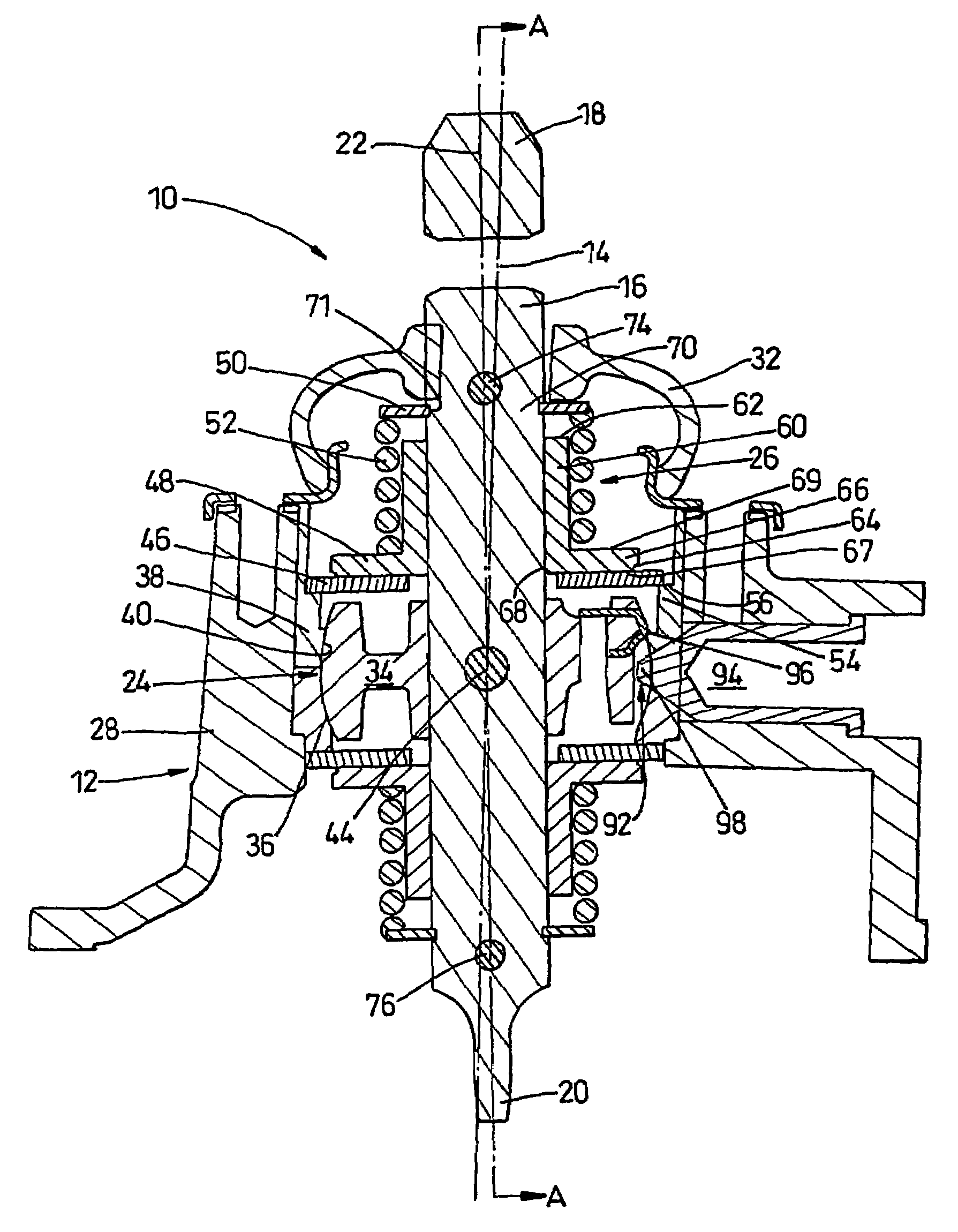
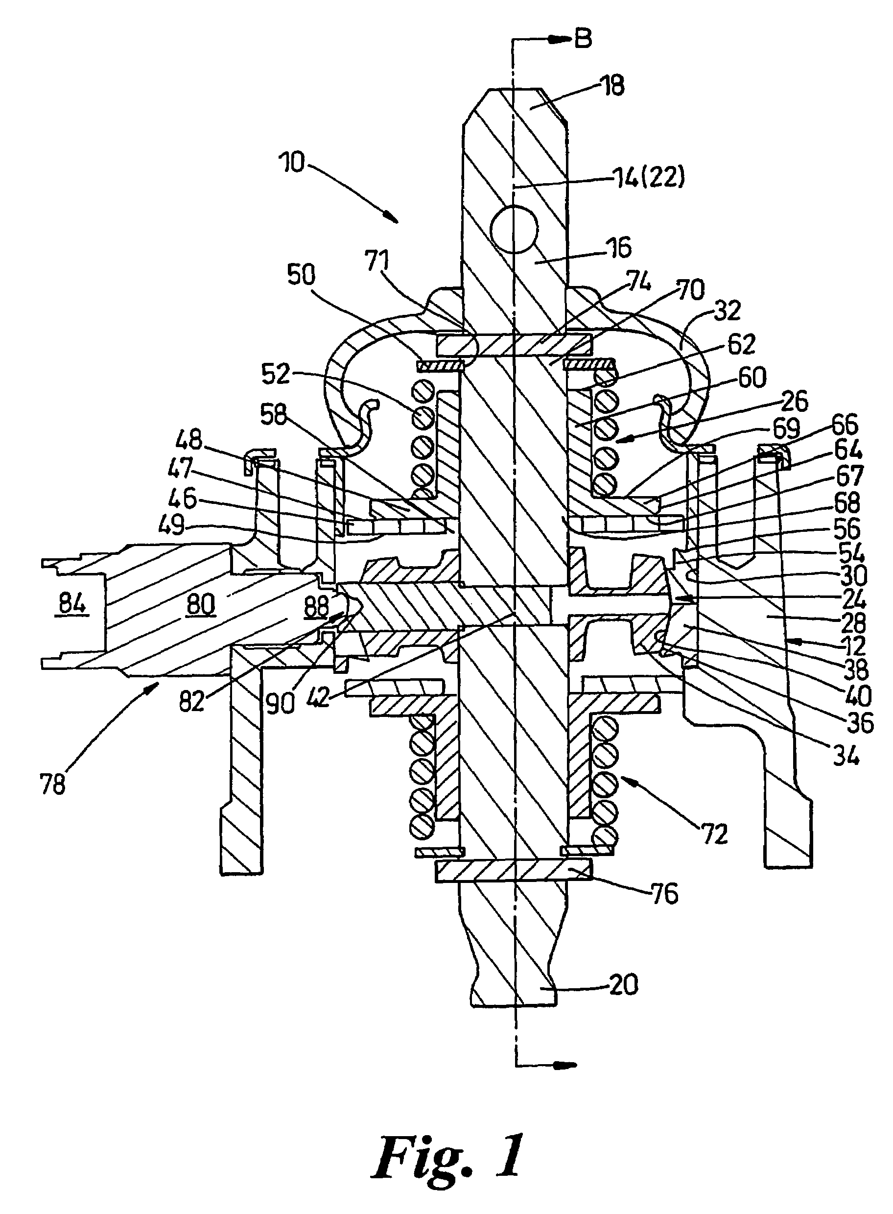
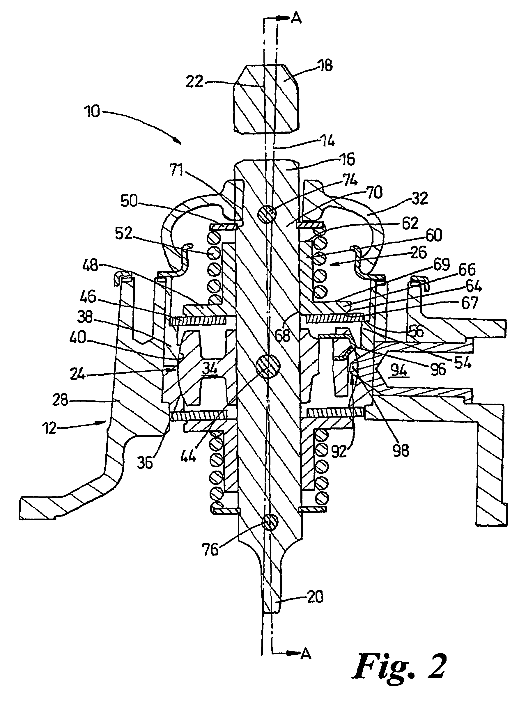
[0042]Referring to the drawings there is shown a shift lever mechanism 10 comprising a housing 12, having a longitudinal axis 14, a lever 16, having a first end 18, a second end 20 and a longitudinal axis 22, pivoting means 24, and biasing means 26.

[0043]The housing 12 is cylindrical, formed around the longitudinal axis 14, and comprises a wall 28, having an inner surface 30, and a cover 32.

[0044]The lever 16 is formed from an elongate member having an external diameter and, in a neutral position, is disposed within the housing 12 along the longitudinal axis 14 thereof.

[0045]The pivoting means 24 comprises a spherical element 34, having an outer spherical surface 36, and a retaining cup 38, having an inner spherical surface 40. The retaining cup 38 is operable to retain the spherical element 34 therein and to provide pivotal displacement of the spherical element 34, about a pivot point 42, by engagement of the outer spherical surface 36 thereof with the inner spherical surface 40 of...


PUM


Abstract

A shift lever mechanism (10) comprises a housing (12), having a longitudinal axis (14), and a lever (16), having a first end (18), a second end (20) and a longitudinal axis (22). The mechanism (10) further comprises pivoting means (24) adapted to facilitate pivoting of the lever (16) into predetermined positions. The mechanism (10) further comprises lever position indication means (78) operable to indicate disposal of the lever in one or more positions, and resilient means (92), operable to provide resistance to displacement of the lever (16) into a predetermined restricted position. The pivoting means (24) is attached to the lever (16) and is disposed in a retaining cup (38), being operable to pivot therein. The retaining cup (38) is disposed in the housing (12). The lever position indication means (78) and the resilient means being disposed on the pivoting means (24).

Description

FIELD OF INVENTION[0001]The present invention relates to gear shift lever mechanisms, particularly to means operable to provide resistance to displacement, and means operable to indicate disposal, of the lever in one or more predetermined positions.BACKGROUND OF THE INVENTION[0002]Normally, the shifting of ratios in a transmission system is effected by a shift finger acting on a set of transmission forks in the transmission. The shift finger is acted on by a shift lever extending outside the transmission and supported in a supporting mechanism.[0003]Conventionally, on a rear driven vehicle, the shift lever is directly operable on the transmission system and is mounted in a housing extending from the top thereof. On a forward driven vehicle, the shift lever is normally remotely operable on the transmission system by means of a remote control shift assembly. The remote control shift assembly normally comprises a series of levers, or other means such as, for example, cables or hydrauli...

Claims


Application Information

Patent Timeline
Patent Type & Authority Patents(United States)
IPC IPC(8): B60K20/00B60K20/02F16H59/04
CPCF16H59/04F16H59/044F16H59/045F16H2059/0295Y10T74/20165F16H2059/0269Y10T74/20159Y10T74/20018F16H2059/6823
Inventor JACKSON, GRAEME ANDREW
Owner EATON CORP
Why Eureka
Eureka Blog
Learn More