Electric connector

a technology of electric connectors and connectors, applied in the direction of coupling contact members, coupling device connections, coupling/disassembly of coupling parts, etc., can solve the problems of lowering the reliability of electric connectors, insufficient insertion guide length and effective fitting length of connection objects, and loss of required elasticity

Inactive Publication Date: 2009-04-28
DAIICHI SEIKO CO LTD
View PDF18 Cites 7 Cited by
  • Summary
  • Abstract
  • Description
  • Claims
  • Application Information

AI Technical Summary

Benefits of technology

[0018]As described above, the electric connector according to the present invention, since such a constitution is adopted that the coupling spring portion connecting the movable beam and the fixed beam is formed in a shape of extending from the joined portion with the fixed beam toward the rear end of the connector in the bending manner, even if the joined portion of the coupling spring portion is disposed at an approximately central portion of the fixed beam, an insertion space for the connection object ahead of the coupling spring space can be secured sufficiently and the distance from the swinging center of the movable beam to the front side contact point of the movable beam and the distance to the actuator operation point are set to be approximately equal to each other, and the operation amount of the actuator to the movable beam and the working amount of the movable beam at the front side contact point are caused to approximately coincide with each other, so that a contact pressure of the movable beam to the connection object is kept approximately constant, contact states of the movable beam and the fixed beam to such a connection object such as an FPC can be kept excellent with a small-sized and simple structure, so that reliability of the electric connector can be considerably improved at a low cost.

Problems solved by technology

As a result, deformation stress generated when the movable beam 1b is displaced so as to be connected with a connection object such as an FPC concentrates on the coupling spring portion 1c and the coupling spring portion 1c plastically deforms, which may result in loss in required elasticity.
In an electric connector adopting such a constitution, however, since the coupling spring portion 1g extending from a fixed beam 1a is formed so as to extend toward a connector front end (a right side in FIG. 6) inserted with a connection object such as an FPC, an arrangement space for the coupling spring portion 1g is expanded and a length of a portion to which a connection object such as an FPC is inserted is shortened, which results in a problem that an insertion guide length and an effective fitting length of a connection object become insufficient.
As a result, large fluctuation in a contact pressure of the movable beam 1b to an FPC occurs, which may result in lowering in reliability of the electric connector.
In that case, however, the insertion space for a connection object can not be secured, as described above.
However, since the fixed beam 1a is fixed to the insulating housing 2 and it is not deformed, a contact pressure to the connection object becomes unstable due to separation of the contact portion 1f at a distal end thereof from the connection object such as an FPC.

Method used


Image

  • Electric connector
  • Electric connector
  • Electric connector

Examples


Embodiment Construction

[0025]Embodiments of the present invention will be explained below in detail with reference to the drawings.

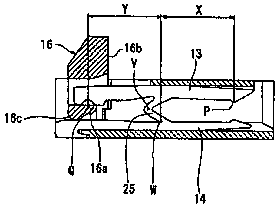
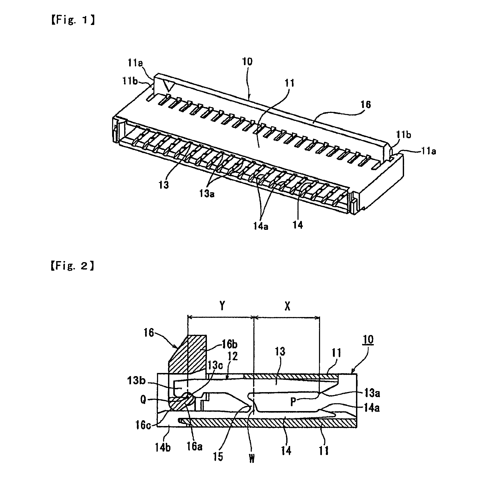
[0026]An electric connector for an FPC 10 according to an embodiment of the present invention shown in FIGS. 1, 2, and 3 includes a hollow insulating housing 11 extending in an elongated shape, and many contacts (electrically conductive terminals) 12 formed of metal members are accommodated inside the insulating housing 11 in a widthwise direction (a longitudinal direction) at proper pitches in a row manner. As shown in FIG. 1, the insulating housing 11 is provided at both ends in its longitudinal direction on its depth side (an upper side in FIG. 1) with projecting portions 11a and 11a, and an actuator 16 is disposed in a space portion formed in an elongated shape at a central portion of the insulating housing in a longitudinal direction thereof.

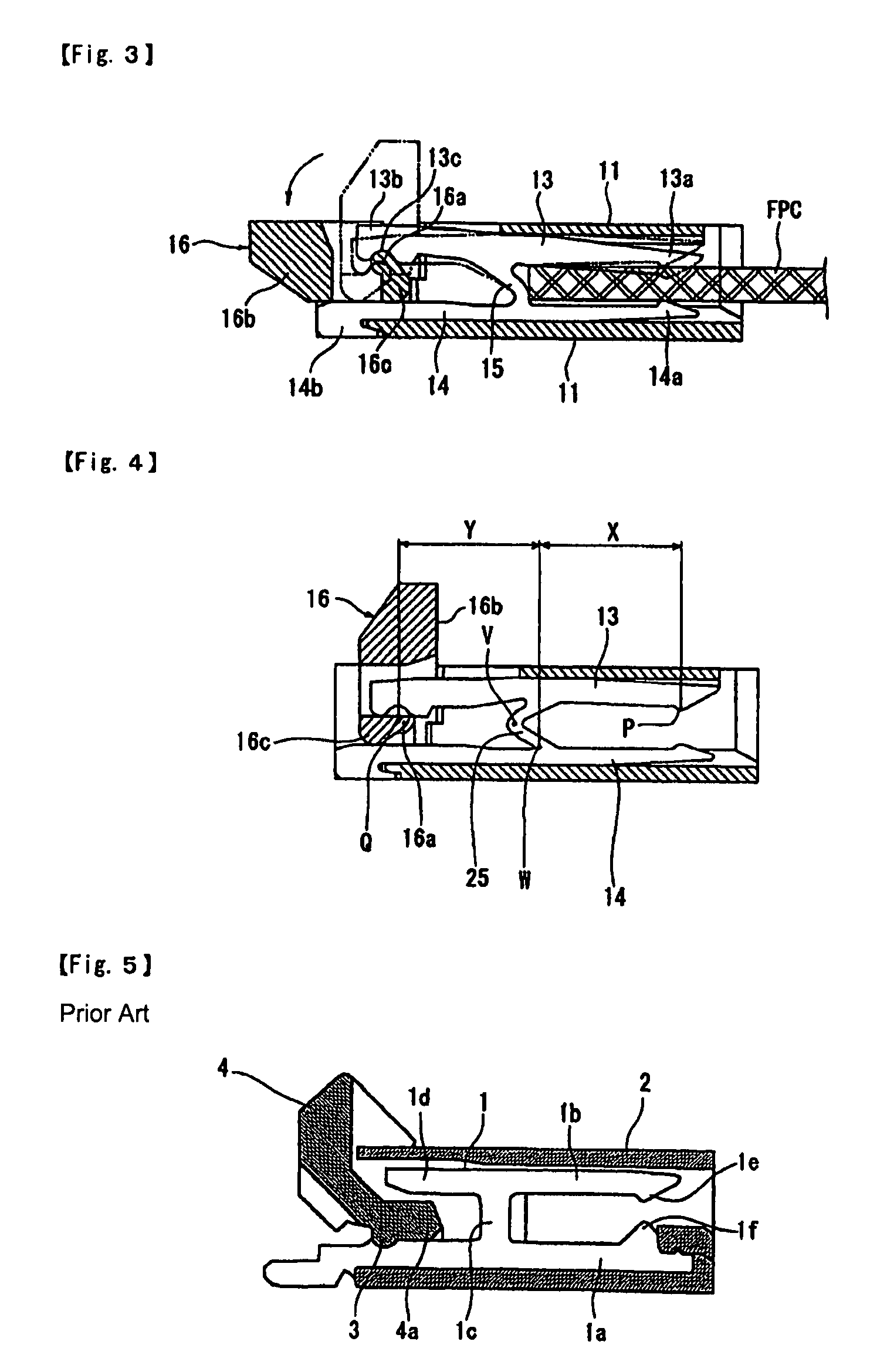
[0027]Each of the contacts 12 has a pair of movable beam 13 and a fixed beam 14 extending from a front end (a right side in FIG. 3) ...


PUM


Abstract

A coupling spring portion 15 connecting a movable beam 13 and a fixed beam 14 is formed in a shape of extending toward a connector rear end in a curved manner, so that, even if a joined portion of the coupling spring portion 15 is disposed at an approximately central portion of the fixed beam 14, an insertion space for a connection object is secured sufficiently. Simultaneously, a distance X from a swinging center W of the movable beam 13 to a front side contact point 13a of the movable beam 13 and a distance Y there from to an actuator operating point Q are set to be approximately equal to each other, so that a contact pressure of the movable beam 13 to the connection object is kept approximately constant by causing an operation amount of the actuator 16 to the movable beam 13 and a working amount of the movable beam 13 at the front side contact point 13a to approximately coincide with each other.

Description

BACKGROUND OF THE INVENTION[0001]1. Field of the Invention[0002]The present invention relates to an electric connector that connects a flexible wiring substrate (FPC), a flexible flat cable (FFC), or the like.[0003]2. Description of the Related Art[0004]As one example of an electric connector of this type, connectors for FPC described in Patent Literature 1 and Patent Literature 2 described below have been known. In a connector for FPC shown in FIG. 5, for example, many flat metal contacts (electrically conductive terminals) with an approximately H shape 1 are attached within a hollow insulating housing 2 in a row manner at proper small pitch, and an actuator 4 is pivotally attached to a rear end of the insulating housing 2 via a pivoting shaft 3.[0005]At that time, each of the above-described contacts 1 has a fixed beam 1a and a movable beam 1b extending in an insertion direction of an FPC which is a connection object, or an object to be connected, (not shown), and the movable beam...

Claims


Application Information

Patent Timeline
Patent Type & Authority Patents(United States)
IPC IPC(8): H01R13/62
CPCH01R12/79H01R13/193H01R12/88
Inventor SHIMADA, YOSHINOBUTATEISHI, JIN
Owner DAIICHI SEIKO CO LTD
Why Eureka
Try Eureka