Shaft for golf clubs and golf club

a technology for golf clubs and shafts, applied in golf clubs, racket sports, sport apparatus, etc., can solve the problems of insufficient strength of shafts, and achieve the effects of avoiding too soft feeling, avoiding too hard feeling, and increasing the head speed s2

Inactive Publication Date: 2009-04-28
DUNLOP SPORTS CO LTD
View PDF15 Cites 26 Cited by
  • Summary
  • Abstract
  • Description
  • Claims
  • Application Information

AI Technical Summary

Benefits of technology

[0130]The present invention is relevant to the bending of shafts, and recovery from the bending. As the shaft overall length L is greater, influence of the bending becomes greater. As the shaft overall length L is greater, the advantage of the present invention is likely to be more explicit. In this respect, the shaft overall length L is preferably equal to or greater than 41 inches (1041 mm), more preferably equal to or greater than 43 inches (1092 mm), still more preferably equal to or greater than 44 inches (1117 mm), and particularly preferably equal to or greater than 45 inches (1143 mm). In light of assurance of the strength of the shaft, the shaft overall length L is preferably equal to or less than 52 inches (1321 mm), more preferably equal to or less than 50 inches (1270 mm), and particularly preferably equal to or less than 48 inches (1219 mm).

Problems solved by technology

The present inventor found another technical problems potentially accompanied by the prior arts.
When the value (b1−bmin) is grater than 35 (N·m2), strength of the shaft may be insufficient.

Method used


Image

  • Shaft for golf clubs and golf club
  • Shaft for golf clubs and golf club
  • Shaft for golf clubs and golf club

Examples


example 1

[0144]A shaft was manufactured according to a sheet winding method. Multiple pieces of the pre-preg were laminated on a mandrel made of metal by wrapping them. A developed view of thus laminated pre-pregs is shown in FIG. 6A. Nine pre-pregs of pre-preg s1, pre-preg s2, pre-preg s3, pre-preg s4, pre-preg s5, pre-preg s6, pre-preg s7, pre-preg s8, pre-preg s9 were wrapped in this order on the mandrel not shown in the figure. The pre-pregs shown on the upper side in FIG. 6A are laminated on the inner side.

[0145]The pre-preg s1 forms a layer that reinforces the tip part. In the pre-preg s1, fiber orientation angle is substantially parallel (0 degree) to the shaft axis line. In other words, the pre-preg s1 constructs a straight layer. The pre-preg s2 is provided along the overall length of the shaft. The pre-preg s2 forms a so called bias layer. In the pre-preg s2, the fiber orientation angle is substantially −45 degree with respect to the shaft axis line. The pre-preg s3 is also provide...

example 2

[0152]Shaft and golf club according to Example 2 were obtained in a similar manner to Example 1 except that brands and constructions of the pre-pregs s1 to s9 were as shown in Table 2.

example 3

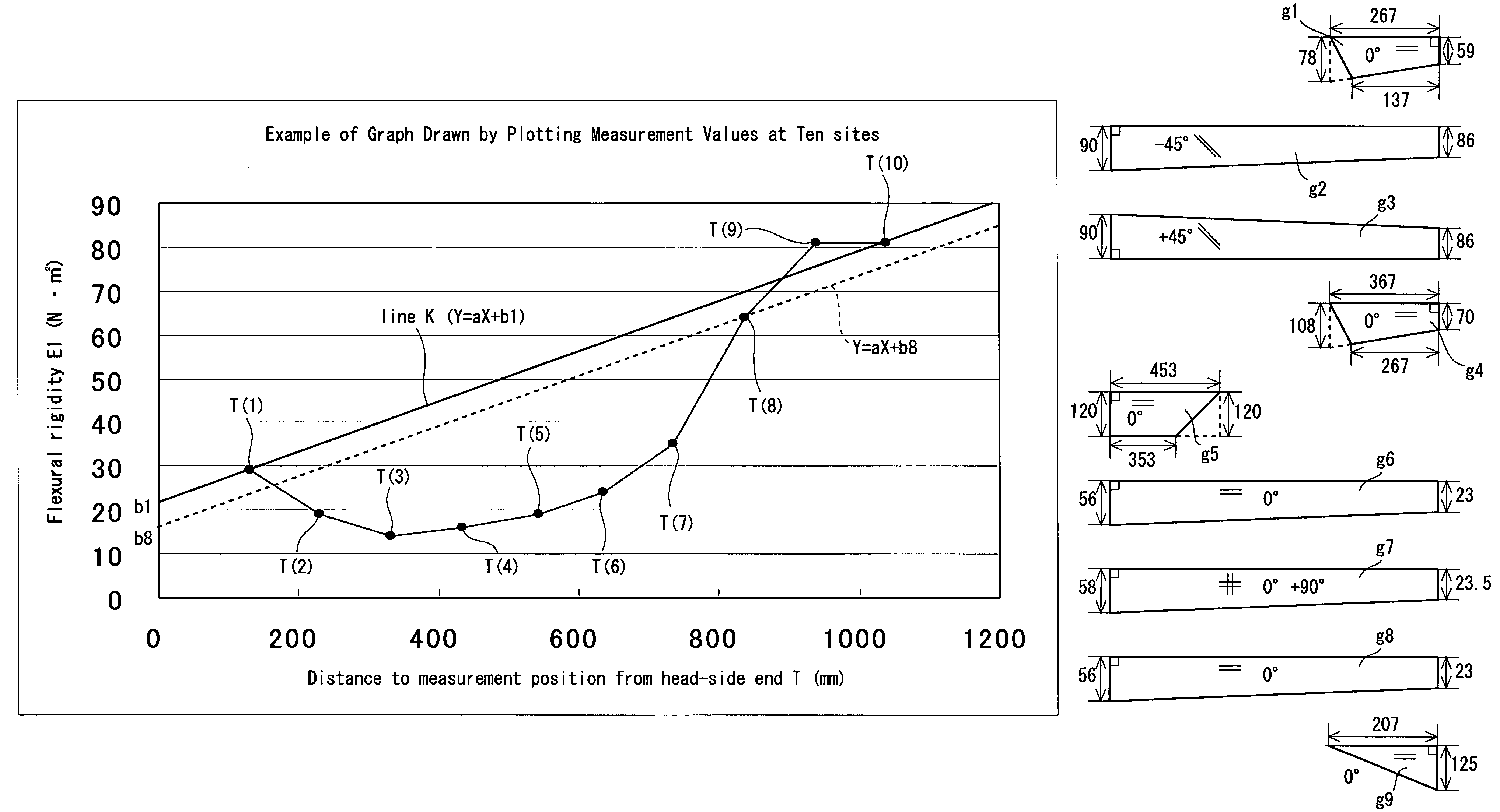
[0156]A shaft was manufactured according to the sheet winding method. Multiple pieces of the pre-preg were laminated on a mandrel made of metal by wrapping them. A developed view of thus laminated pre-pregs is shown in FIG. 6B. Nine pre-pregs of pre-preg g1, pre-preg g2, pre-preg g3, pre-preg g4, pre-preg g5, pre-preg g6, pre-preg g7, pre-preg g8, pre-preg g9 were wrapped in this order on the mandrel not shown in the figure. The pre-pregs shown on the upper side in FIG. 6B are laminated on the inner side.

[0157]The pre-preg g1 forms a layer that reinforces the tip part. In the pre-preg g1, fiber orientation angle is substantially parallel (0 degree) to the shaft axis line. In other words, the pre-preg g1 constructs a straight layer. The pre-preg g2 is provided along the overall length of the shaft. The pre-preg g2 forms a so called bias layer. In the pre-preg g2, the fiber orientation angle is substantially −45 degree with respect to the shaft axis line. The pre-preg g3 is also provi...


PUM


Abstract

Points obtained by plotting flexural rigidity EI measured at ten sites on a shaft are defined as from T (1) to T (10) in this order from the head side, and the formula representing a line K that passes the T (1) and the T (10) is defined as [Y=aX+b1]. The values at the Y-intercepts on the lines that are parallel to the line K and that pass the points of from T (2) to T (9), respectively, are defined as from b2 to b9, respectively, and the minimum value among the values at the Y-intercepts b2 to b9 is defined as bmin. Slope “a” of the line K is 0.04 or greater and 0.06 or less; every one of the b3, b4, b5, b6, b7 and b8 is smaller than b1; and the bmin is any one of b4 to b7. The value (b1−bmin) is 30 (N·m2) or greater and 40 (N·m2) or less, and the value (b9−b1) is 4 (N·m2) or greater and 15 (N·m2) or less. This shaft either has a high-strength straight layer and a hoop layer, or has a textile layer.

Description

[0001]This application claims priority on Patent Application No. 2006-252088 filed in JAPAN on Sep. 19, 2006, and Patent Application No. 2006-337326 filed in JAPAN on Dec. 14, 2006. The entire contents of these Japanese Patent Applications are hereby incorporated by reference.BACKGROUND OF THE INVENTION[0002]1. Field of the Invention[0003]The present invention relates to shafts for golf clubs and golf clubs.[0004]2. Description of the Related Art[0005]In recent years, carbon shafts, which are generally referred to, have been used as the shafts for golf clubs. In the carbon shafts, carbon fiber having high specific strength and specific rigidity has been used. As the specific strength and specific rigidity of the carbon fiber increases, manufacture of lightweight shafts for golf clubs has been enabled.[0006]During swing, the shaft is bent or twisted. Behavior of the shaft during swing may vary depending on rigidity distribution of the shaft. JP-A-2003-169871 and JP-A-2005-34550 discl...

Claims


Application Information

Patent Timeline
Patent Type & Authority Patents(United States)
IPC IPC(8): A63B53/10
CPCA63B53/10A63B59/0014A63B2209/023A63B60/10A63B60/06A63B60/08
Inventor KUMAMOTO, TOMIO
Owner DUNLOP SPORTS CO LTD
Why Eureka
Try Eureka