Vibration motor

a vibration motor and motor body technology, applied in the field of vibration motors, can solve the problems of reducing the influence of heat on the vibration motor, making it difficult for the vibration motor to tilt forward to the weight side, and reducing the rotational radius of the weigh

Inactive Publication Date: 2007-10-18
COPAL CO LTD
View PDF5 Cites 23 Cited by
  • Summary
  • Abstract
  • Description
  • Claims
  • Application Information

AI Technical Summary

Benefits of technology

[0011]As a vibration motor becomes smaller, a shift of the position of an overall center of gravity increases, making the weight side more likely to tilt forward on a wiring board when mounted. However, since the vibration motor has a pair of forward tilting prevention portions extending up to the position facing the weight formed on the weight side at the bottom of the holder, the vibration motor is made more difficult to tilt forward to the weight side, with the forward tilting prevention portions acting as a support, stabilizing a seat of the vibration motor on the wiring board when mounted. As a result, the vibration motor can reliably be soldered to the wiring board by reflow-soldering and a soldered portion can be made more unlikely to separate even if a dropping impact is received. In addition, further miniaturization of a small vibration motor is demanded, while on the other hand, upsizing of the weight is demanded as well. Thus, a notch is provided between a pair of forward tilting prevention portions on the center line extending along the bottom, and therefore the radius of rotation of the weight can be increased by board thickness at the bottom by the notch. This enables upsizing of the weight in the centrifugal direction. If the radius of rotation of the weight can be increased by board thickness even though the board thickness of the bottom is, for example, less than 0.5 mm, the weight can have a very great influence on overall vibration by increasing the radius of rotation of the weight only slightly due to smallness of the vibration motor. Consequently, the present invention is very effective in promoting miniaturization of the vibration motor.
[0012]A slit extending from the end in the direction of the center line of the notch to the rear end of the bottom is preferably formed at the bottom of the holder. A slit is formed in a holder when forming the holder, and therefore the holder easily broadens outwardly by the slit. Thus, by providing a slit to a bottom side placed on a wiring board, the slit can be arranged on the wiring board when mounting a motor and thus broadening of the slit can be stopped with solder while simultaneously soldering the bottom and wiring board. Therefore, even when the vibration motor receives a dropping impact, it becomes possible to prevent broadening of the holder and to appropriately avoid a motor part from protruding from the holder.
[0013]It is preferable that the holder be formed in a rectangular cross-sectional shape from a bottom, a pair of flanks erected from both sides of the bottom, and a top bridging the flanks, and claws that are in contact with an outer surface of the case and bias the case toward an inner wall surface of the top are provided on the pair of flanks. The holder has a rectangular cross-sectional shape and thus if, for example, a cylindrical case is surrounded by the holder, an area where the case and holder are in contact will become smaller. As a result, it becomes harder to conduct heat to the case via the holder when soldering the holder to the wiring board, reducing an influence of heat on the vibration motor. Further, since claws that are in contact with an outer surface of the case and bias the case toward an inner wall surface of the top are provided on a pair of flanks, the case is lifted in a direction away from the bottom to separate the bottom from the case, and as a result, an influence of heat on the vibration motor can be reduced when soldering the bottom to the wiring board. Further, since the top of the holder is planate, suction by an adsorption nozzle of a mounting machine can be maintained in an excellent state.
[0014]The forward tilting prevention portions preferably have the flanks erected continuously from the holder. The flanks are erected in such a manner, and therefore material strength such as flexural strength and impact strength can be increased when compared with a case in which the forward tilting prevention portions are formed solely of flat plates.
[0017]As a vibration motor becomes smaller, a shift of the position of the overall center of gravity increases, making the weight side more likely to tilt forward on a wiring board when mounted. Since the vibration motor has a pair of forward tilting prevention portions extending up to the position facing the weight formed on the weight side at the bottom of the holder, the vibration motor is made more difficult to tilt forward to the weight side, with the forward tilting prevention portions acting as a support, stabilizing the seat of the vibration motor on the wiring board when mounted. Also, a notch is provided between a pair of forward tilting prevention portions on the center line extending along the bottom and the radius of rotation of the weight can be increased by board thickness at the bottom by the notch. This enables upsizing of the weight in the centrifugal direction.

Problems solved by technology

However, since the vibration motor has a pair of forward tilting prevention portions extending up to the position facing the weight formed on the weight side at the bottom of the holder, the vibration motor is made more difficult to tilt forward to the weight side, with the forward tilting prevention portions acting as a support, stabilizing a seat of the vibration motor on the wiring board when mounted.
As a result, it becomes harder to conduct heat to the case via the holder when soldering the holder to the wiring board, reducing an influence of heat on the vibration motor.

Method used


Image

  • Vibration motor
  • Vibration motor
  • Vibration motor

Examples


Embodiment Construction

[0030]A suitable embodiment of a vibration motor according to the present invention will be described in detail below with reference to drawings.

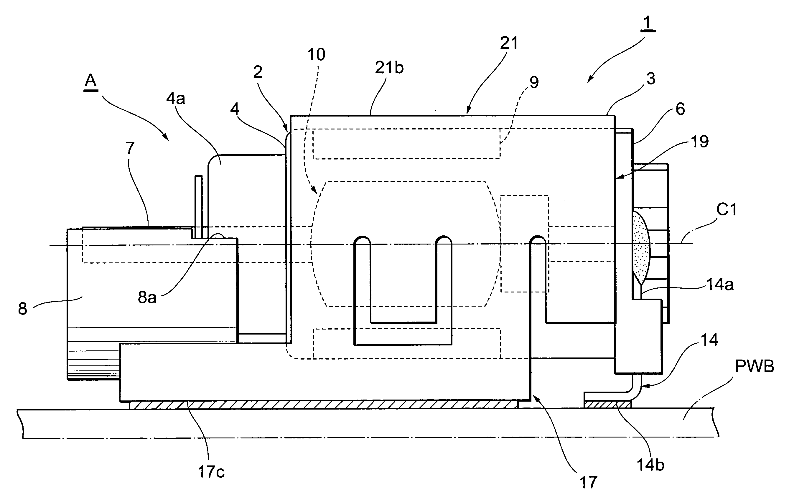
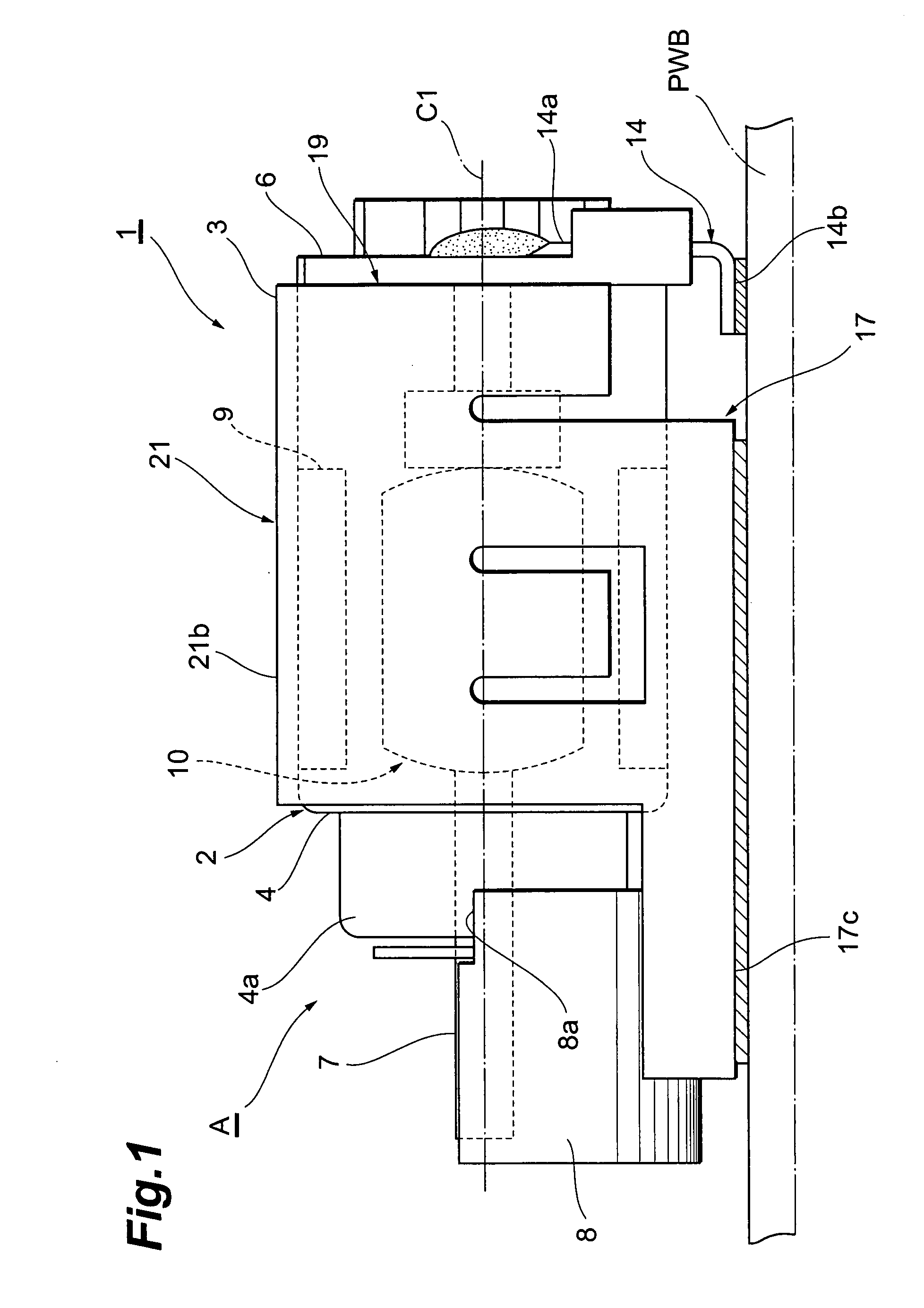
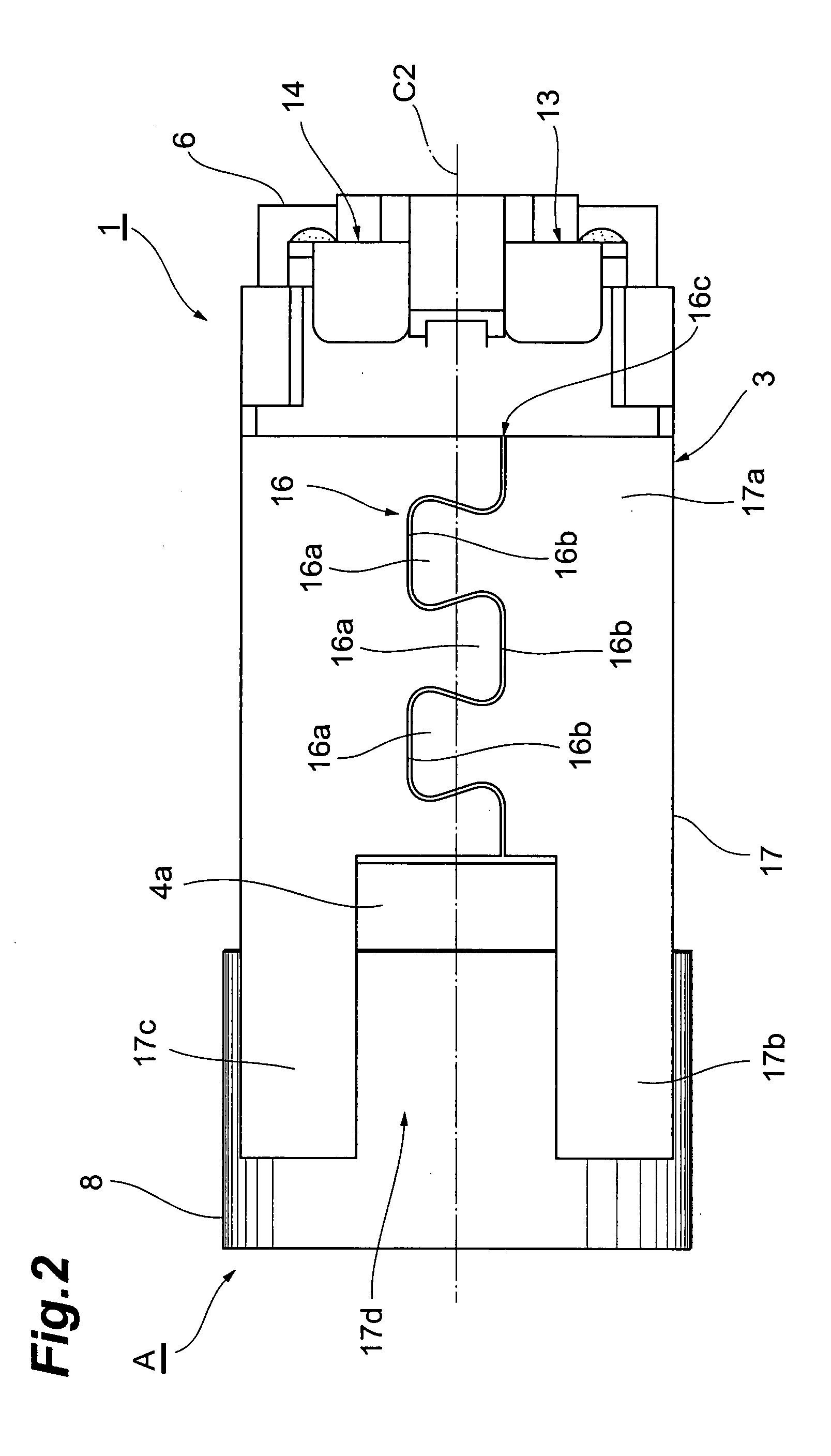
[0031]As shown in FIG. 1 to FIG. 4, a vibration motor 1 is a small vibration motor surface-mounted on a printed wiring board PWB by reflow-soldering, and includes a motor part A having a tubular case 2 of about 4 mm in diameter and about 10 mm in length and a holder 3 in a tubular and rectangular cross-sectional shape into which the tubular case 2 is press-fitted.

[0032]The tubular case 2 is comprised of a metallic cylindrical housing 4 and a resin bracket 6 press-fitted into an open rear end of the housing 4. A protruding neck 4a is formed by contraction on the front end side of the housing 4 and a portion of a shaft 7 protrudes from the front end of the neck 4a. A weight 8 whose cross section is fan-shaped is eccentrically fixed to the end of the shaft 7 by crimping or press fitting. A dent 8a into which a portion of the neck 4a is fitted ...


PUM


Abstract

A vibration motor having a tubular case, a shaft protruding from a front end of the case, a weight eccentrically fixed to an end of the shaft, and a metallic holder surrounding the case, the holder being surface-mounted on a wiring board by reflow-soldering, wherein the holder has a planate bottom placed on the wiring board, a pair of forward tilting prevention portions that extends up to a position facing the weight is formed at the bottom, a notch is provided on a center line extending along the bottom between the forward tilting prevention portions, and the notch extends from the front end of the forward tilting prevention portions beyond the position facing the weight.

Description

BACKGROUND OF THE INVENTION[0001]1. Field of the Invention[0002]The present invention relates to a vibration motor incorporated in various communication apparatuses (for example, mobile phones), game machines, or massaging equipment and to be used as a vibration generating source.[0003]2. Related Background of the Invention[0004]A vibration motor has, for example, an approximately cylindrical case arranged along a direction of an axis of rotation of a shaft and a weight is eccentrically fixed to a tip of the shaft protruding from a front end of the case. A rotor and stator are accommodated in the case. A coil of the rotor is connected to a commutator and a brush slidingly contacts with the commutator. A terminal, which is connected to the brush and protrudes out of the case, is in contact with a conductor on a printed wiring board to receive power. Then, a current flows from the terminal to the coil through the brush and commutator, torque of the rotor is generated to rotate the sha...

Claims


Application Information

Patent Timeline
Patent Type & Authority Applications(United States)
IPC IPC(8): H02K11/00H02K7/06H02K5/00
CPCH02K5/00H02K2211/03H02K7/061H02K5/225H02K7/075H02K7/065
Inventor SUZUKI, KAZUHISASEGAWA, NOBORU
Owner COPAL CO LTD
Why Eureka
Try Eureka