
Plasma display apparatus

a technology of plasma display and display panel, which is applied in the direction of static indicating devices, instruments, television systems, etc., can solve the problem of high brightness of images, and achieve the effect of preventing burns on the plasma display panel

Inactive Publication Date: 2009-04-28
FUNAI ELECTRIC CO LTD
View PDF5 Cites 12 Cited by
  • Summary
  • Abstract
  • Description
  • Claims
  • Application Information

AI Technical Summary

Benefits of technology

[0011]The present invention has been made in view of the above problems and an object of the present invention is to provide a plasma display apparatus wherein a burn in on the plasma display panel can be prevented without causing the viewer to feel uncomfortable with a change in the viewing image.

Problems solved by technology

Generally, the cause of a burn-in on a plasma display panel is, for example, that a displayed image does not change for a long time, or that the brightness of an image is high.

Method used


Image

  • Plasma display apparatus
  • Plasma display apparatus
  • Plasma display apparatus

Examples


Embodiment Construction

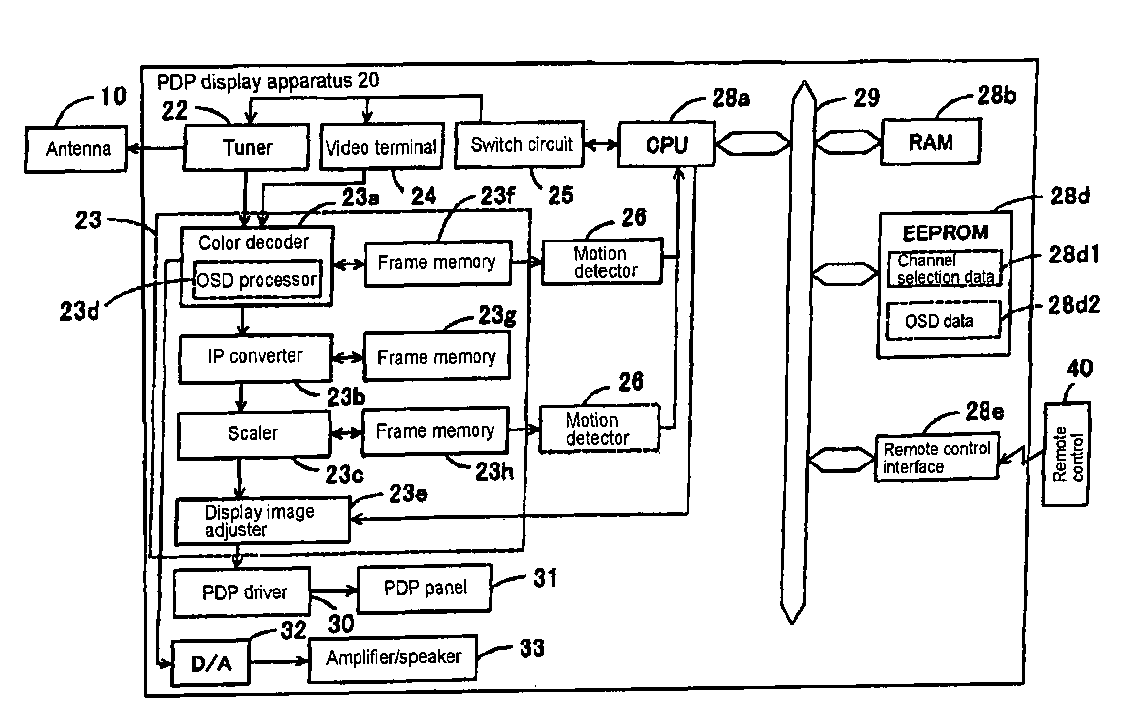
[0049]Preferred embodiments of the present invention will be described below in the following order:[0050](1) Configuration of a plasma display apparatus[0051](2) Description of a screen saver function[0052](3) Description of a time interval setting function[0053](4) Description of the operation[0054](5) Variations[0055](6) Conclusion

[0056](1) Configuration of a plasma display apparatus:

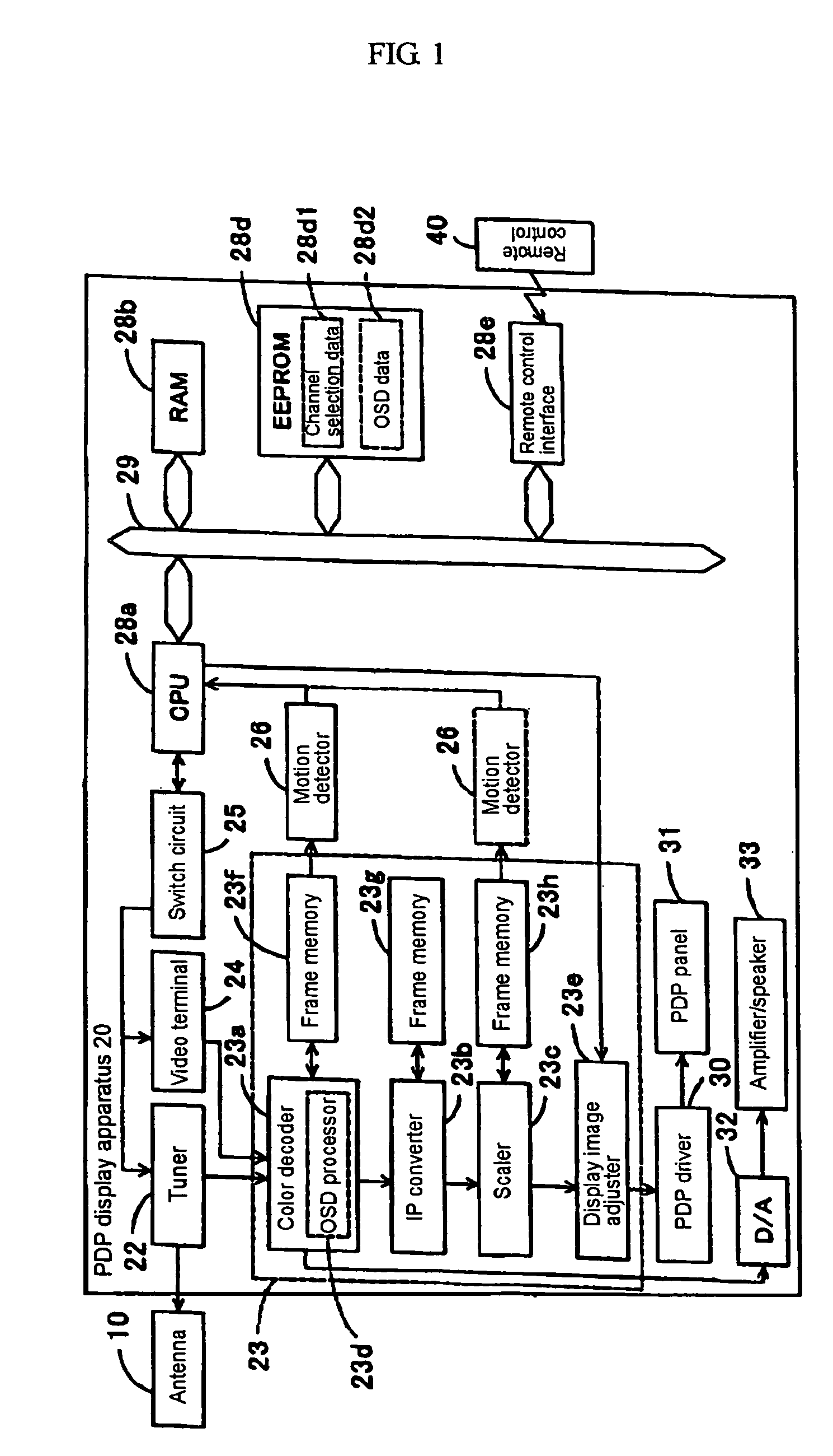
[0057]FIG. 1 is a block diagram showing the configuration of a display apparatus (plasma display television) that is a television provided with a plasma display panel (PDP) according to the present invention. In this figure, a PDP display apparatus 20 contains a tuner 22 to which a frequency signal is input from an antenna 10. The tuner 22 is a so-called synthesizer type tuner wherein PLL data, i.e. frequency division ratio data from the variable frequency divider circuit in a PLL loop is fed to the tuner 22, as a channel selection control signal.

[0058]The PDP display apparatus 20 has a video input t...


PUM


Abstract

According to the present invention, a CPU 28a shifts target pixels in steps S305, S310, and S335, and at the same time references the image data in a frame memory 23f and checks whether the image is inactive, based on the difference in successive images, and whether the pixels are bright, based on the image data, in steps S320 and S325 respectively. When the image is liable to burn-in, a variable DF is incremented and a time interval t1 is updated every 5 minutes, the time interval t1 is being set shorter for an image liable to burn-in, i.e. the amount of motion is small and many pixels are bright, and set longer for an image not liable to burn-in, i.e. the amount of motion is large and many pixels are dark, at this time.

Description

BACKGROUND OF THE INVENTION[0001]1. Field of the Invention[0002]The present invention relates to a plasma display device and more specifically to a plasma display apparatus that prevents a burn-in on the panel.[0003]2. Description of the Prior Art[0004]Conventionally, there is a screen saver function that prevents a burn-in on a screen by shifting an image being displayed up, down, right, and left on the screen by the specified number of pixels at regular intervals. The screen saver shifts the image being displayed at a predetermined interval, and therefore the user can set the shifting interval.[0005]Also, as a technology to prevent a burn-in on a panel when a still image continues to be displayed, there is known the technology to display a screen saver produced from an video image, as disclosed in Japanese Patent Laid-Open No. 2004-015288 (Patent document 1).[0006]Furthermore, for prevention of a burn-in when an image including moving portions is being displayed, there is known th...

Claims


Application Information

Patent Timeline
Patent Type & Authority Patents(United States)
IPC IPC(8): G09G3/28G09G5/10G09G3/20G09G3/291G09G3/296H04N5/66
CPCG09G3/007G09G3/20G09G3/28G09G2320/046G09G2320/106G09G2340/0464
Inventor OHNO, SHINICHI
Owner FUNAI ELECTRIC CO LTD
Learn More