
Night vision compatible display backlight

a technology of night vision and backlight, which is applied in the direction of landing aids, instruments, lighting support devices, etc., can solve the problems of increasing the cost of lcd screens, prone to failure unexpectedly, and limited ability to change brightness levels

Active Publication Date: 2009-04-28
ASTRONAUTICS CORPORATION OF AMERICA
View PDF30 Cites 74 Cited by
  • Summary
  • Abstract
  • Description
  • Claims
  • Application Information

AI Technical Summary

Benefits of technology

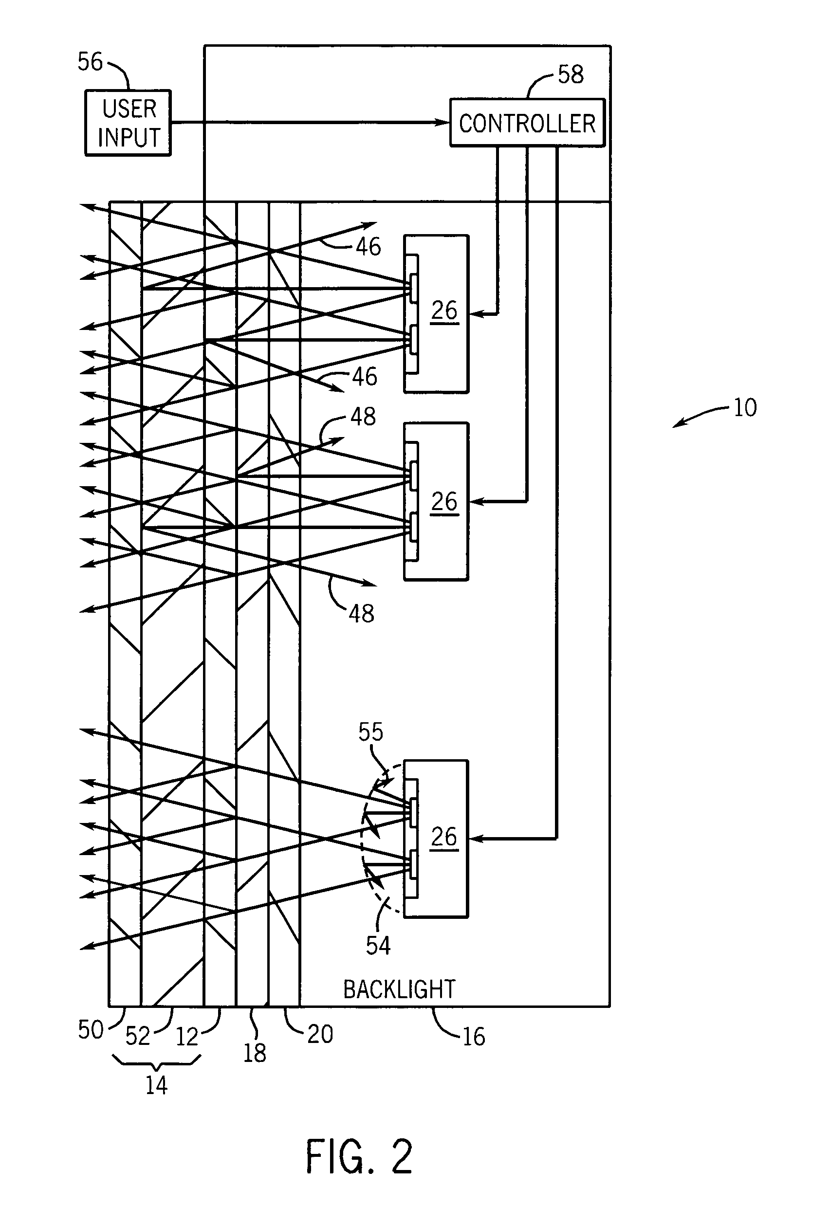
"The present invention provides a system and method for backlighting a display using LEDs that does not require filters and meets NVIS standards. The system includes an array of LEDs with at least one red, green, and blue LED, and a controller that selectively illuminates the LEDs to produce an illumination compatible with NVIS standards during a night vision mode and a non-night vision mode. The method includes activating a set of LEDs during the first operating mode and activating a different set of LEDs during the second operating mode. The intensity of light emitted during the second operating condition complies with a night vision standard for viewing the LCD display. The technical effects of the invention include improved visibility and compatibility with night vision standards for viewing displays."

Problems solved by technology

For example, fluorescent tube backlights generally require a high voltage power supply, include fragile glass tubes, have a tendency to fail unexpectedly, and have a limited ability to change brightness levels.
Unfortunately, these filters add significantly to the cost of the LCD screens.
Furthermore, these filters often impede portions of the visible spectrum range and / or viewing angle in which case, the LCD screen may appear “unnatural” to an operator especially when viewed in daylight.
The effectiveness of an interference type filter varies at different viewing angles, causing further loss of visible light.
While this may compensate for the decreased intensity, the additional heat generated by the increased power consumption places strain on cooling systems.
Furthermore, the additional power consumption may be undesirable in many applications such as avionics when a fixed supply of power is available.

Method used


Image

  • Night vision compatible display backlight
  • Night vision compatible display backlight
  • Night vision compatible display backlight

Examples


Embodiment Construction

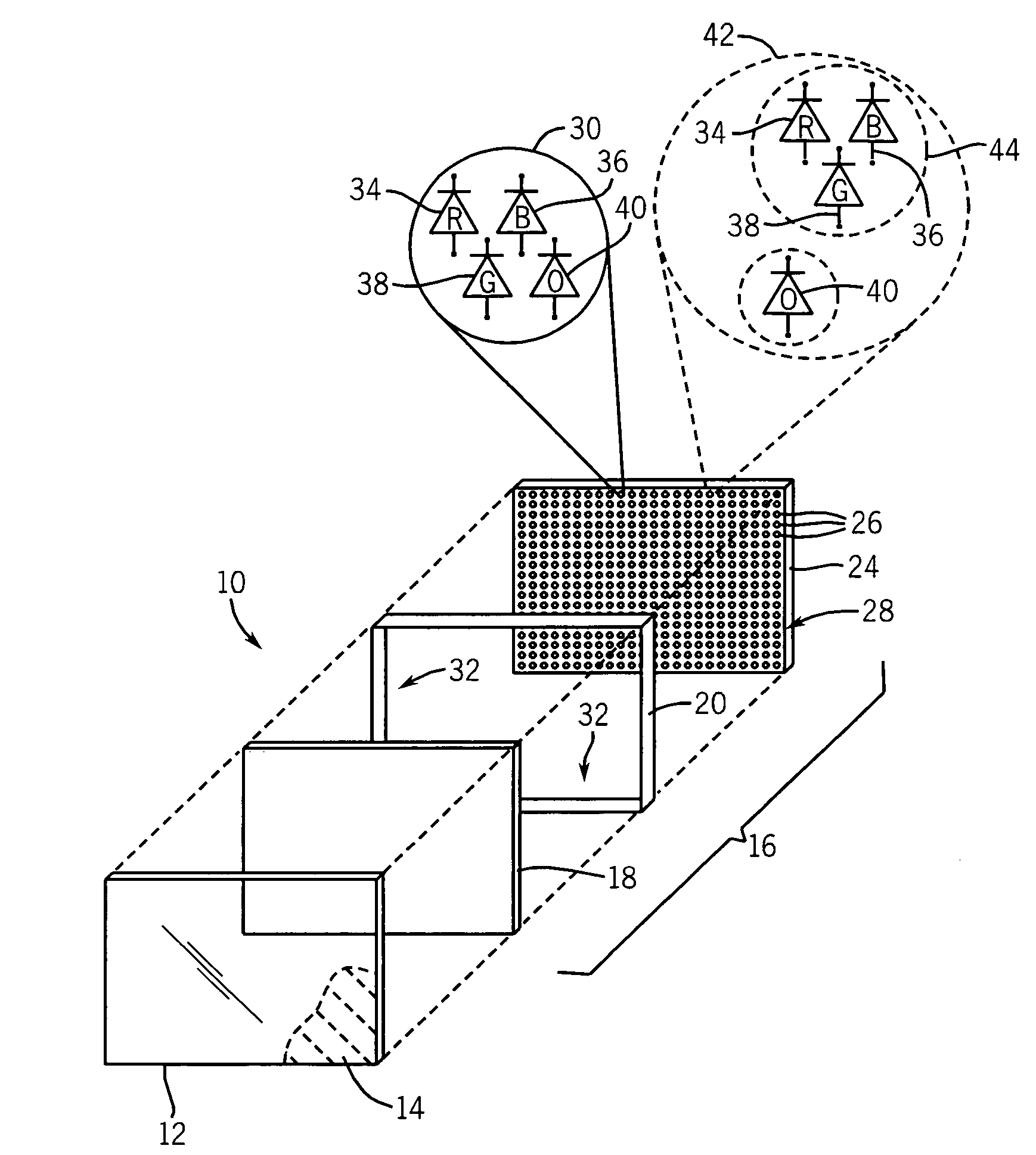
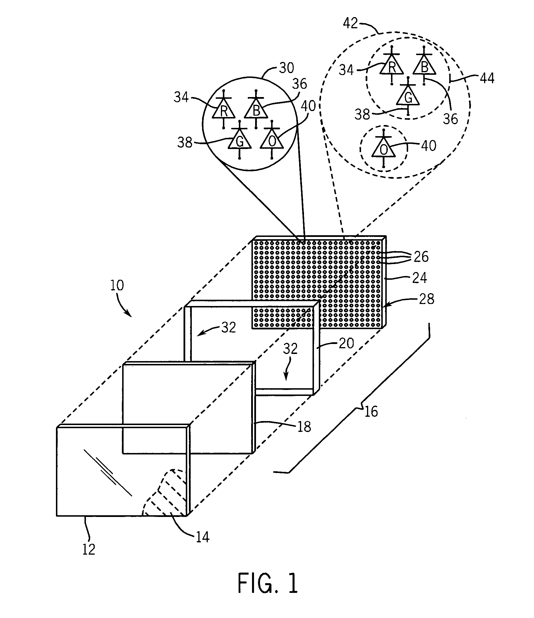
[0027]Referring now to FIG. 1, a display system 10, for example an avionics display system, includes a liquid crystal display (“LCD”) 12 designed to produce graphic representations of, for example, avionics indicator gauges. As will be described, the LCD 12 may include an optional filter 14. The filter 14 may provide electromagnetic interference (“EMI”) shielding, radio frequency interference (“RFI”) shielding, antiglare / antireflective functionality, and / or contrast enhancement. Additionally, as will be described, the filter 14 may filter radiation in a lower NVIS band and / or upper NVIS band.

[0028]Arranged rearwardly of the LCD 12 is a backlight assembly 16 including a diffuser 18, a mixing assembly 20, and a matrix or array of light-emitting diodes (“LEDs”) 24. The diffuser 18 is positioned between the LED array 24 and the LCD screen 12, and serves to spread light from many point source LEDs in the LED array 24. The diffuser 18, may, for example, also include a lens or holographic ...


PUM

PropertyMeasurementUnit
near infrared transmittanceaaaaaaaaaa
wavelengthaaaaaaaaaa

Abstract

A system and method of backlighting a display using LEDs is night vision viewing compatible and requires no filters. The backlight includes an array of LEDs and a controller configured to selectively illuminate the LEDs in the array. The array of LEDs includes orange LEDs that are illuminated during a night vision viewing mode and may include red LEDs that are illuminated in a non-night vision viewing mode.

Description

CROSS-REFERENCE TO RELATED APPLICATIONSSTATEMENT REGARDING FEDERALLY SPONSORED RESEARCH OR DEVELOPMENTBACKGROUND OF THE INVENTION[0001]The present invention relates generally to a backlight for a display and, in particular, to a light emitting diode (“LED”) backlight for a display that is compatible with night vision systems.[0002]Graphic displays, such as those employing a liquid crystal display (“LCD”) screen provide a field of pixel elements, each of which may be independently controlled to block or pass light, for example, from an underlying backlight.[0003]A common backlight for use with an LCD screen provides a transparent panel edge lit by one or more fluorescent tubes. A reflective rear surface of the panel directs the edge illumination towards an LCD screen positioned against a front surface of the panel. The reflective rear surface of the panel may be gradated to produce an even field of illumination behind the LCD screen to compensate for an inherent falloff of brightness...

Claims


Application Information

Patent Timeline
Patent Type & Authority Patents(United States)
IPC IPC(8): G02F1/1335
CPCB60K35/00G01D11/28G02F1/133603B60K2350/203G02F2001/133626G02F1/133626B60K2360/33B60K35/10B60K35/80B60K35/22
Inventor ZAGAR, PETER A.ULIJASZ, THADDEUS RAYMOND
Owner ASTRONAUTICS CORPORATION OF AMERICA
Learn More