Fluorine-doped optical fiber

a fluorine-doped optical fiber and optical fiber technology, applied in the field of optical fiber transmission, can solve the problems of increased transmission loss, optical loss of signals transmitted in the fiber, and inability to use conventional ssmf fiber in optical communication systems installed, and achieve the effect of improving resistance to high-dose radiation

Active Publication Date: 2009-04-28
DRAKA COMTEQ BV
View PDF10 Cites 72 Cited by
  • Summary
  • Abstract
  • Description
  • Claims
  • Application Information

AI Technical Summary

Benefits of technology

[0014]For this purpose, the present invention proposes an optical fiber whose refractive index profile is uniformly depressed with respect to the profile of a standard single mode fiber (SSMF). The transmission characteristics of the optical fiber substantially meet the standard G.652B and show an improved resistance to high-dose radiation (e.g., doses of more than 100 Gy).
[0021]Typically, the fluorine content in the depressed core is 1.4 weight percent or less. This fully satisfies the needs for a transmission fiber having reduced transmission losses under high radiation but retains compatibility with the G.652B standard for single-mode fiber.

Problems solved by technology

The signal transmitted in the fiber undergoes optical losses that accumulate over the distance traveled.
These transmission losses increase when the fiber is subjected to ionizing radiation, such as beta, alpha, gamma and X radiation.
A conventional SSMF fiber, therefore, is not suitable for use in an optical communications system installed in an environment having high doses of ionizing radiation (e.g., higher than 100 to 1,000 Gy).
The prior art fibers show some resistance to ionizing radiation but nevertheless have high losses under strong radiation, particularly over and above 400 Gy.

Method used


Image

  • Fluorine-doped optical fiber
  • Fluorine-doped optical fiber
  • Fluorine-doped optical fiber

Examples


first embodiment

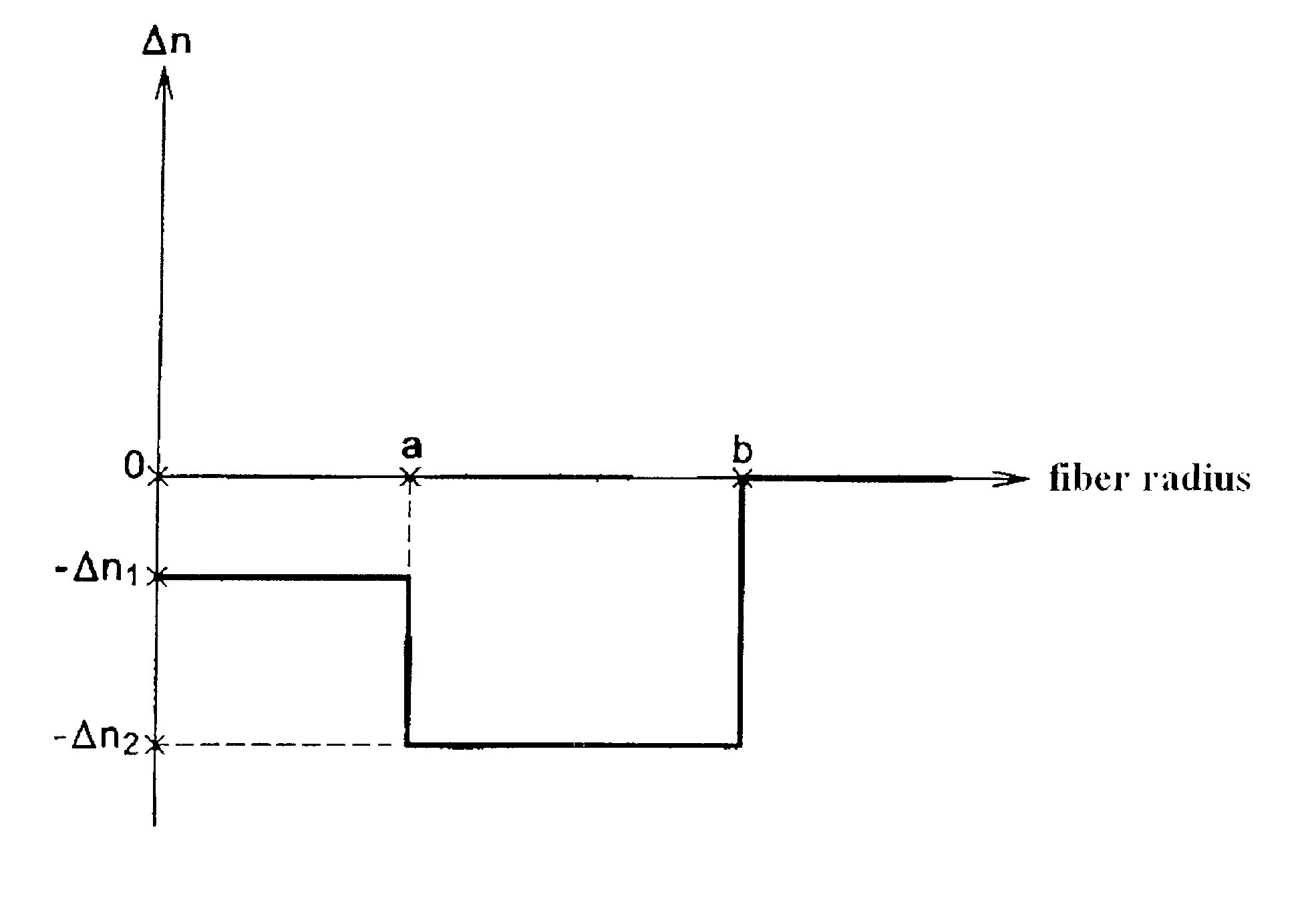
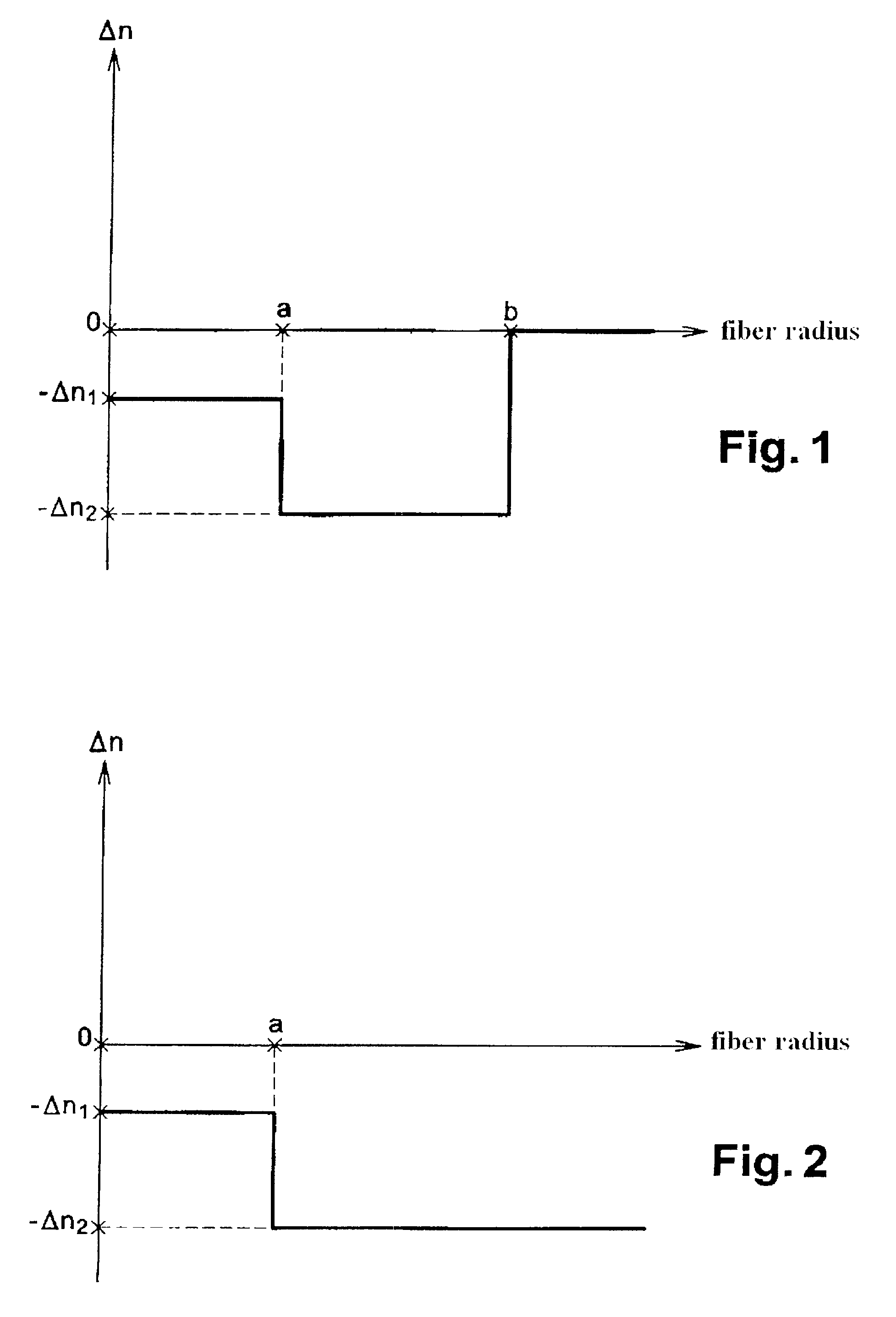
[0031]FIG. 1 illustrates a refractive index profile for a transmission fiber according to the present invention. The illustrated profile is a set profile (i.e., representing a theoretical profile of the fiber). The fiber actually obtained after drawing from a preform might have a slightly different profile.

[0032]The transmission fiber of the invention includes a central depressed core having an absolute refractive index difference |Δn1| with pure silica (which is sometimes used on the outside of the fiber to act as an outer optical cladding), and a depressed cladding having an absolute refractive index difference |Δn2| with pure silica. The refractive indexes in the depressed core and the depressed cladding are substantially constant longitudinally. This imparts longitudinally uniform properties to the fiber. The central core is represented with a radius, a, and the depressed cladding extends between the radial values a and b. See FIG. 1.

[0033]To define a set refractive index profil...

second embodiment

[0035]FIG. 2 illustrates an index profile for a transmission fiber according to the present invention. In this fiber embodiment, the fiber core contains 0.54 weight percent fluorine but no germanium and no phosphorus, and the cladding contains 1.9 weight percent fluorine. The core has a radius, a, of 4.35 microns and an absolute refractive index difference |Δn1| with silica of 2.0×10⁻³. The cladding has an absolute refractive index difference |Δn2| with silica of 7.0×10⁻³. Fluorine doping is typically uniform in the core and the cladding.

[0036]According to this second embodiment, the fiber is fabricated from a primary preform produced by deposition inside a fluorine-doped tube having substantially the same refractive index as the target depressed cladding. The outer cladding may be a sleeved tube of fluorine-doped silica or an overcladding of fluorine-doped silica particles. Techniques for fabricating primary preforms for fibers of the invention are described hereinafter.

[0037]The a...


PUM

PropertyMeasurementUnit
wavelengthaaaaaaaaaa
mode field diameteraaaaaaaaaa

Abstract

A single mode optical transmission fiber comprises a depressed core having at least 0.41 weight percent fluorine and an index difference (|Δn1|) with pure silica greater than 1.5×10⁻³, a depressed cladding having at least 1.2 weight percent fluorine and an index difference (|Δn2|) with pure silica greater than 4.5×10⁻³ and an index difference (|Δn2|−|Δn1|) with the depressed core greater than or equal to 3×10⁻³.

Description

CROSS-REFERENCE TO PRIORITY APPLICATION[0001]This application hereby claims the benefit of pending French Application No. 06 / 06058 (filed Jul. 4, 2006, at the French Patent Office), which is hereby incorporated by reference in its entirety.FIELD OF THE INVENTION[0002]The present invention relates to optical fiber transmissions and, more specifically, to a fluorine-doped optical fiber.BACKGROUND OF THE INVENTION[0003]The refractive index profile of optical fibers is generally qualified in relation to the plotting of a graph that shows the function associating the refractive index of the fiber with the radius of the fiber. Conventionally, the distance, r, to the center of the fiber is shown along the abscissa axis, and the difference between the refractive index of the fiber core and the refractive index of the fiber cladding is shown along the ordinate axis. The index profile is therefore described as “step,”“trapezoid,” or “triangular” for graphs, showing, respectively, step, trapez...

Claims


Application Information

Patent Timeline
Patent Type & Authority Patents(United States)
IPC IPC(8): G02B6/036G02B6/00
CPCC03C13/046G02B6/02G02B6/03633
Inventor MATTHIJSSE, PIETERGOOIJER, FRANSFLAMMER, IVOREGNIER, ELISEKUYT, GERARD
Owner DRAKA COMTEQ BV
Why Eureka
Try Eureka