J-channel backer material

a backer material and j-channel technology, applied in the direction of joints tightening/covering, covering/lining, construction, etc., can solve the problems of inability to effectively and aesthetically apply caulk, inability to accurately fit the window or door frame into the masonry veneer or cavity wall construction, and inability to meet the thickness, geometry and dimensions of the masonry, etc., to achieve convenient use and efficient and reliable

Active Publication Date: 2009-05-05
TY DAS BUILDING PROD LLC
View PDF24 Cites 26 Cited by
  • Summary
  • Abstract
  • Description
  • Claims
  • Application Information

AI Technical Summary

Benefits of technology

[0007]This invention provides a solution to these and other problems in the art and allows an efficient and reliable installation for a water tight and an aesthetically pleasing transition from surrounding the window or door to the masonry veneer. Generally, in one embodiment this invention includes a backer unit or finishing member installed adjacent the J-channel window frame or door frame to provide a proper transition from the frame to the masonry wall structure. In one embodiment, the finishing member has a generally L-shaped configuration with a first leg of the member being mounted in the cavity defined by the channel of the J-channel frame. The second leg of the finishing member projects generally perpendicularly from the first leg and between the forward edge of the window or door J-channel frame and the masonry outer wall. In one embodiment, the first leg is frangibly joined to the second leg by a perforated joint for selective separation of the second leg from the first leg.
[0008]After the finishing member is installed adjacent to the frame and the inner and outer wall construction is complete, the terminal end portion of the second leg is removed by being torn along the frangible joint. After the terminal end portion is removed, a recess is exposed at a juncture with the frame and the remainder of the finishing member. A bead of caulk or similar finishing material is applied in the recess to provide a smooth and aesthetically pleasing transition from the J-channel frame to the masonry wall. Additionally, the juncture between the frame and the wall is sealed by the caulk bead to inhibit and / or prevent the entry of moisture or other foreign material and the void in the J-channel is substantially filled.
[0009]Advantageously, the finishing member is readily adaptable for use with a wide variety of window and door J-channel or other frame designs and construction specifications without requiring highly skilled or specialized installation and construction techniques.

Problems solved by technology

Problems often arise during construction, however, in maintaining a proper transition between the wall structure and window, door and other openings or discontinuities in the wall.
For example, the dimensioning of the window or door frame installed in the wall is frequently different and incompatible with the thickness, geometry and dimensions of the masonry veneer or cavity wall construction.
However, due to the incompatibility of the J-channel frame with the masonry veneer, effective and aesthetic caulk application is nearly impossible.
As a result, the detailing and finishing work required for proper installation of a window or door into a masonry veneer or cavity wall construction is typically very labor intensive, non-uniform and highly dependent upon the skill and experience of the particular contractor or tradesman performing the installation particularly when a J-channel is used.

Method used


Image

  • J-channel backer material
  • J-channel backer material
  • J-channel backer material

Examples


Embodiment Construction

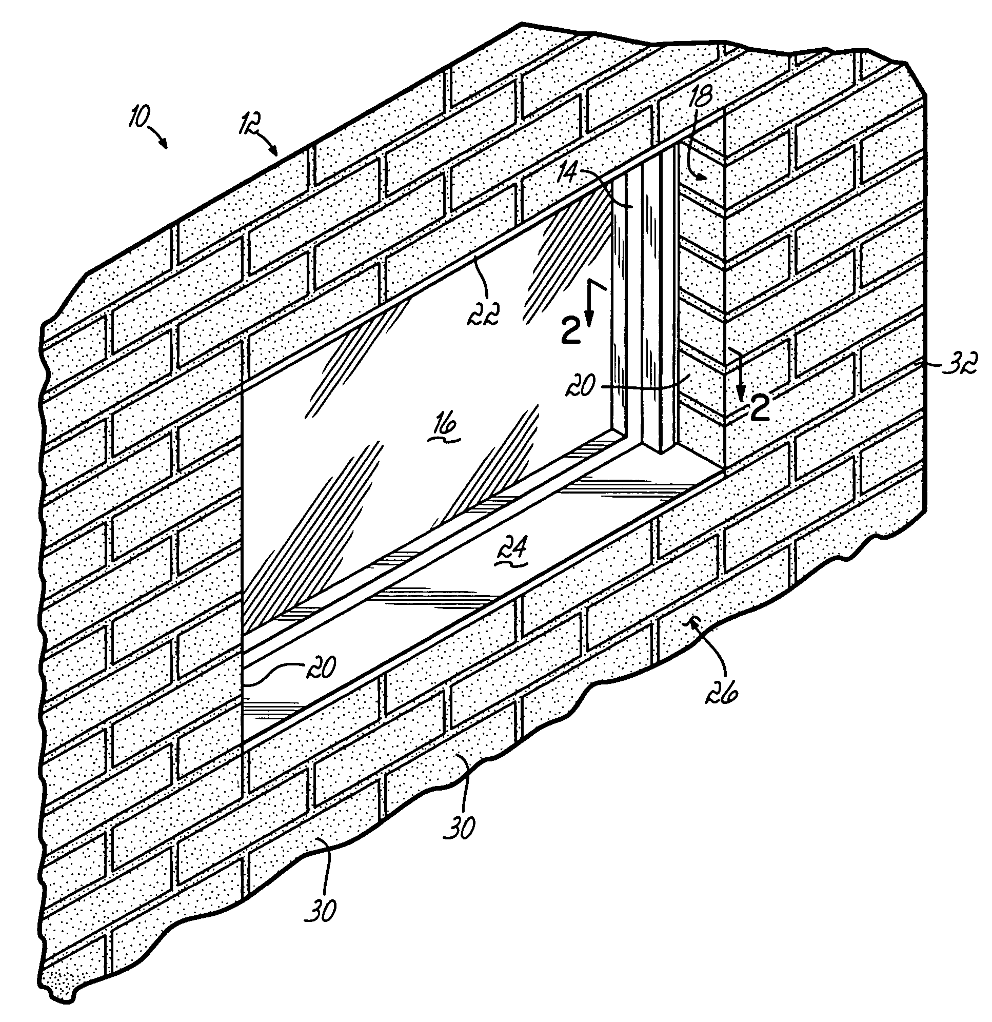
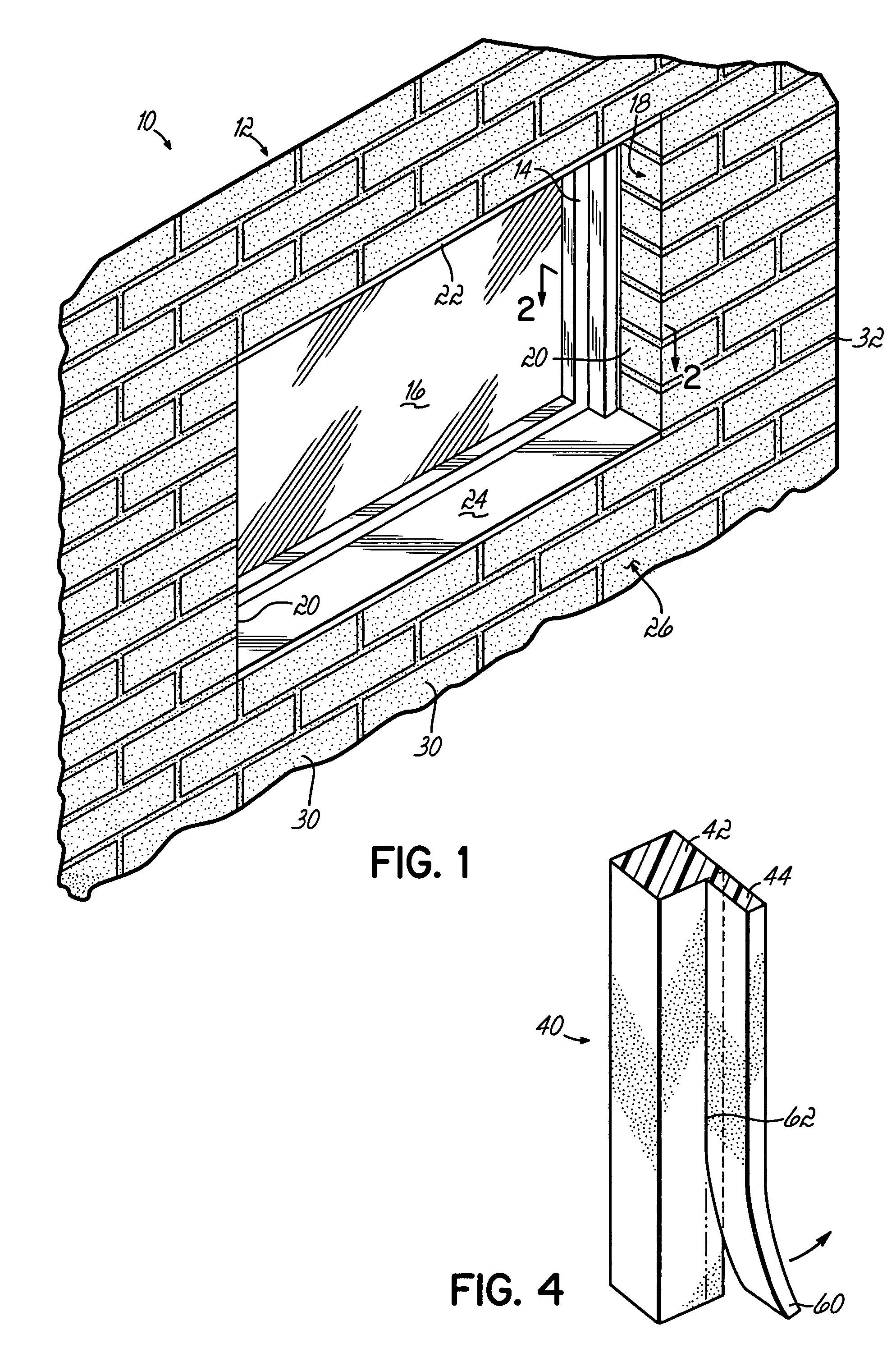
[0015]Referring to FIG. 1, an exemplary window installation 10 in a masonry wall 12 is shown. The window installation 10 includes a perimeter window frame 14, one or more window panes 16, and a window opening 18 in the wall defined by a pair of jambs 20 and a header 22 above and a sill 24 below the window frame 14. Although one example of a window installation is shown in FIG. 1, this invention is readily applicable for a variety of closure elements in openings in the wall such as other types of window installations, frame designs, doors and the like.

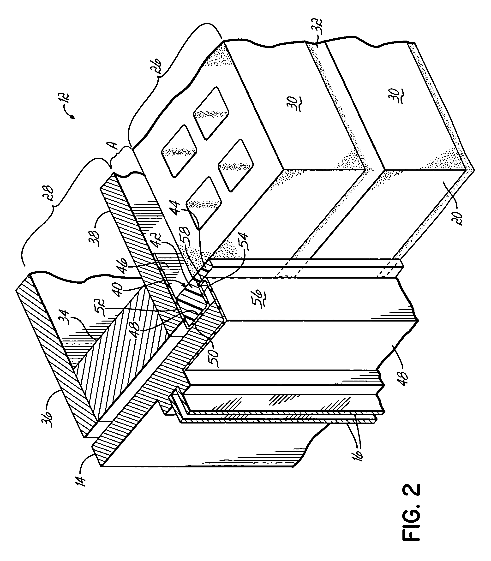
[0016]As shown more clearly in FIGS. 2-3, the masonry wall 12 for the exterior of a building, in one embodiment, is comprised of an outer wall of masonry or brick veneer 26 and an insulated interior wall 28. The brick veneer outer wall 26 is constructed from a plurality of bricks or blocks 30 arranged in a vertical pattern. Each brick 30 is of a substantially rectangular shape having a uniform length, height and depth. The brick veneer ...


PUM


Abstract

A finishing member for masonry walls allows for simple installation and accurate placement of caulking around windows and doors in cavity wall construction. This invention accommodates a wide variety of window or door frame profiles, particularly those having an outwardly directed channel such as so called J-channel frames, for the detailing and finishing work required for proper installation of a window or door into a masonry veneer or cavity wall construction without requiring a highly skilled and labor intensive installation.

Description

[0001]This is a continuation in part of U.S. patent application Ser. No. 10 / 602,198 filed Jun. 24, 2003, now abandoned which in turn claims the benefit of U.S. Provisional Patent Application Ser. No. 60 / 391,333, filed Jun. 25, 2002, each of which is hereby incorporated by reference entirely.BACKGROUND OF THE INVENTION[0002]This invention relates to masonry veneer or cavity wall construction and, more particularly, to devices used in association with window and door installations in a veneer / cavity wall system for proper transition between the window or door installation and the masonry veneer.[0003]Wall systems having a masonry exterior are typically constructed of at least one vertical layer of masonry and at least a second vertical layer of a material forming a back-up system. The back-up system may be constructed of lumber, light gauge steel studs or of a concrete masonry unit. The masonry and back-up system are typically bonded together by horizontal metallic ties spaced apart v...

Claims


Application Information

Patent Timeline
Patent Type & Authority Patents(United States)
IPC IPC(8): E06B1/04E04F13/06E06B1/62
CPCE06B1/62
Inventor COLLINS, P. MICHAEL
Owner TY DAS BUILDING PROD LLC
Why Eureka
Try Eureka