Check patentability & draft patents in minutes with Patsnap Eureka AI!

Vehicle with actively adjustable axle system

a technology of axle system and vehicle, which is applied in the direction of vehicle body stabilisation, transportation and packaging, bicycles, etc., can solve the problems of inability to directly steer the vehicle operator, the ground-interacting dolly wheels themselves, and the inability of the vehicle operator to direct the vehicle, etc., to facilitate the movement interaction

Inactive Publication Date: 2009-05-05
INTEGRATED VISION
View PDF11 Cites 11 Cited by
  • Summary
  • Abstract
  • Description
  • Claims
  • Application Information

AI Technical Summary

Benefits of technology

"The present invention provides a vehicle with an actively adjustable axle system that can adjust the position of the wheels to maintain stability over uneven terrain. The vehicle includes a frame and an adjustable axle assembly mounted to the frame. The adjustable axle assembly has a pair of wheels and an actuation system that can adjust the position of the wheels relative to the frame and the body of the vehicle. The vehicle also includes a body with an adjustable axle assembly mounted to it. The adjustable axle assembly has a fore-aft position that can be adjusted to actively maintain stability. The vehicle can be used as an automotive vehicle, recreational vehicle, agricultural vehicle, construction vehicle, military vehicle, or robotic vehicle. The vehicle also includes an electronic controller that can communicate with the actuation system to adjust the position of the wheels as necessary to maintain stability. The vehicle can also include one or more load sensors, position sensors, and attitude sensors to further improve stability and control."

Problems solved by technology

Thus, the two ground-interacting dolly wheels themselves are, by design, not capable of being directly steered by the vehicle operator.
Although a ZT vehicle has the inherent advantage and desirable characteristic of having such zero turn capability, a ZT vehicle also has some inherent disadvantages and undesirable characteristics as well.
Second, the typical ZT vehicle, as described hereinabove, includes two ground-interacting dolly wheels mounted to the front portion of the frame that provide no directional stability for the front end of the vehicle.
Third, since the “uphill” drive wheel of the vehicle naturally has less traction than the “downhill” drive wheel of the vehicle due to the incline of the hill effectively shifting more of the vehicle weight to the downhill drive wheel, the uphill drive wheel is prone to losing traction and therefore slipping.
When such slipping occurs, the directional stability normally provided by the uphill drive wheel is lost, thereby causing the front end of the vehicle to be gravitationally pulled sideways and downhill.
However, a problem sometimes arises when the ZT vehicle attempts to travel directly up a steep hill.
In particular, if the incline of a hill is sufficiently severe, the front end of the ZT vehicle comes off the ground as the overall weight and center of gravity of the vehicle shifts rearward and beyond the points of contact between the two drive wheels and the ground.
Furthermore, even if the incline of a hill is not so severe, a sudden burst of acceleration by the ZT vehicle as initiated by a vehicle operator while driving the vehicle also frequently causes the front end of the vehicle to come off the ground.
In extreme cases of these two types of situations, the front end of the ZT vehicle sometimes comes off the ground to the extent that the vehicle is altogether upended.
However, such remedial fixtures have proven to be undesirable in cases where the front end of the vehicle comes off the ground for prolonged periods of time, for the fixtures in such cases give rise to drag that significantly inhibits rather than facilitates uphill travel.
However, such a manually adjustable ballast system has proven to be largely inconvenient to use when traveling over unanticipated or unknown terrain with extreme and everchanging topography or grade characteristics.
Furthermore, such a manually adjustable ballast system has also proven to be largely inconvenient to use whenever frequent and significant changes in the human load and / or the object load onboard the vehicle are made.
Although such elongated track assemblies are effective in improving the overall fore-aft stability of the vehicle when traveling over extreme and everchanging terrain, the inherent elongated nature of the track assemblies undesirably limits, in some situations, the zero turn capability of the vehicle.
In addition, given the typical variation in fore-aft (i.e., front-to-back) loading of a ZT vehicle, each elongated track assembly often fails to properly interact with the ground in an even pressure-distributed manner along its respective length, thereby undesirably negating a characteristic advantage of utilizing such elongated track assemblies on terrain with, for example, sand or snow.
Although such a ZT vehicle with gyroscopic sensor system is reasonably effective in maintaining vehicle balance under most conditions, such is only marginally effective under conditions of reduced traction.
For example, if an area of ground on a hillside is significantly covered with sand, loose gravel, mud, water, snow, or ice, a ZT vehicle with gyroscopic sensor system sometimes has difficulty in maintaining its balance while traveling thereon.
Such difficulty is due to the fact that good traction necessary for drive wheel movement to quickly correct any vehicle imbalance is not always available under such reduced traction conditions.

Method used


Image

  • Vehicle with actively adjustable axle system
  • Vehicle with actively adjustable axle system
  • Vehicle with actively adjustable axle system

Examples


first embodiment

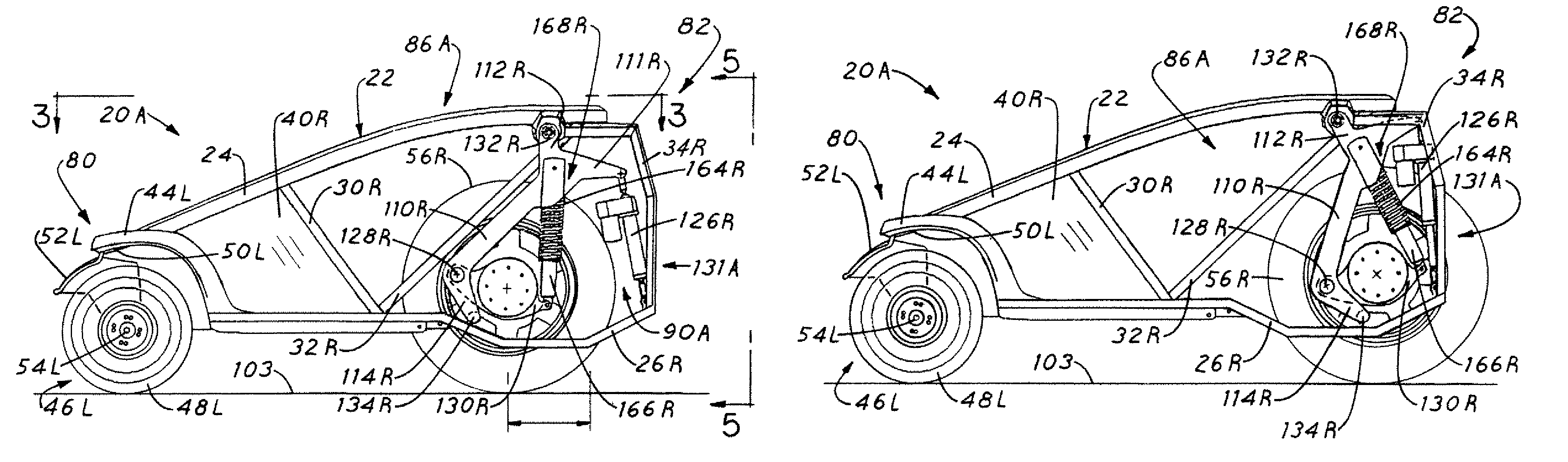
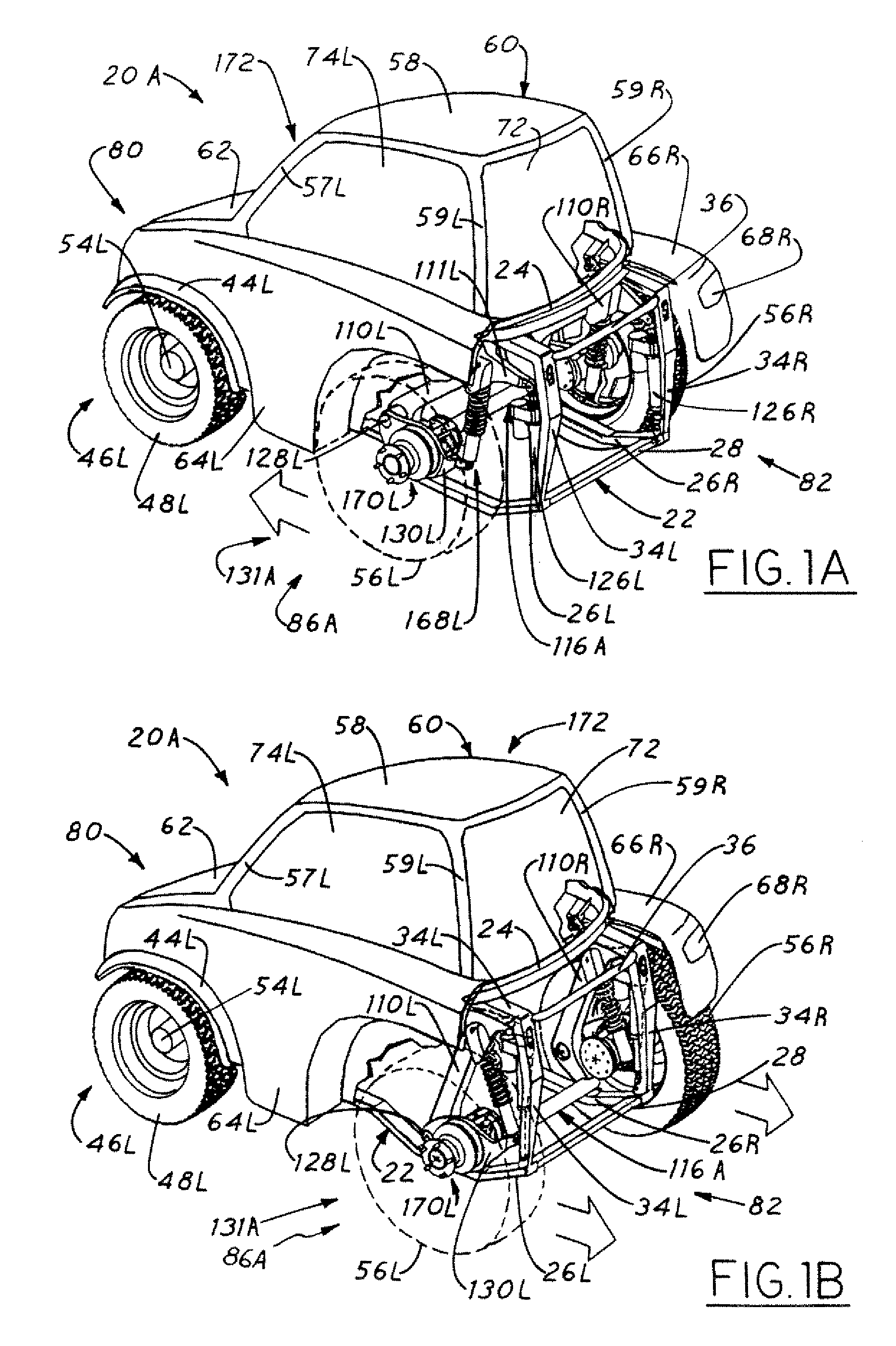
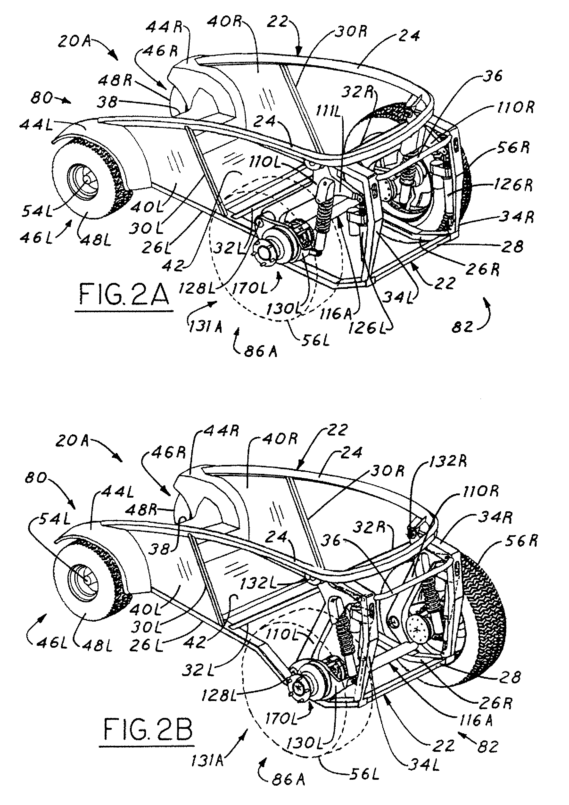
[0043]FIGS. 1A through 6B illustrate a first embodiment 20A of the vehicle 20 according to the present invention. The vehicle 20A is a zero turn (ZT) vehicle that includes, as particularly illustrated in FIG. 3, a frame 22 having an associated front end 80, a rear end 82, and a fore-aft axis 84 extending therebetween. The frame 22 itself includes a plurality of support members 24, 26L, 26R, 28, 30L, 30R, 32L, 32R, 34L, 34R, 36, and 38 and also a plurality of support panels 40L, 40R, and 42 assembled together as particularly illustrated in FIGS. 2A, 2B, 3, 5, 6A, and 6B. It is to be understood, however, that such support members and support panels may alternatively be formed as an integral whole. In addition to the frame 22, the vehicle 20A also includes a body 60 that is mounted to the frame 22. The body 60 itself optionally includes a roof panel 58, left and right front roof panel support members (only the left front roof panel support member 57L is shown), left and right rear roof...


PUM


Abstract

A vehicle with an actively adjustable axle system suitable for traveling over even or uneven terrain with a load is herein proposed. The vehicle includes a frame having a front end, a rear end, and a fore-aft axis extending therebetween; a body mounted to the frame; an adjustable axle assembly mounted to the frame such that the adjustable axle assembly is aligned substantially orthogonal to the fore-aft axis; a pair of wheels rotatably mounted on the ends of the adjustable axle assembly such that the wheels are aligned substantially in parallel and are thereby capable of facilitating moving interaction with the ground; at least one supplemental ground-interacting apparatus mounted to the frame such that each supplemental ground-interacting apparatus cooperates with the pair of wheels to thereby maintain clearance between both the frame and the body and the ground; an actuation system capable of mechanically adjusting the adjustable axle assembly to thereby adjust the fore-aft position of the pair of wheels relative to both the frame and the body; and an electronic controller mounted to the body and electrically connected to the actuation system. In such a configuration, the electronic controller is capable of communicating electrical control signals to the actuation system to thereby adjust the fore-aft position of the pair of wheels as necessary to actively maintain the fore-aft stability of the vehicle.

Description

CROSS-REFERENCE TO RELATED APPLICATION[0001]The present invention claims priority from U.S. Provisional Application Ser. No. 60 / 392,329, originally entitled “Moveable Axle for Vehicle Stability,” which was filed on Jun. 28, 2002.FIELD OF THE INVENTION[0002]The present invention generally relates to road vehicles, off-road vehicles, or all-terrain vehicles (ATVs) suitable for traveling over even or uneven terrain. The present invention more particularly relates to vehicles having at least one axle assembly shared by two wheels suitable for use as, for example, automotive vehicles, recreational vehicles, agricultural vehicles, utility vehicles, construction vehicles, military vehicles, or robotic vehicles.BACKGROUND OF THE INVENTION[0003]A “zero turn” (ZT) vehicle, as is commonly known in the art, will in some embodiments typically include, for example, a frame, a power source, a body, a primary axle assembly, two drive wheels, and two dolly wheel assemblies. The power source is commo...

Claims


Application Information

Patent Timeline
Patent Type & Authority Patents(United States)
IPC IPC(8): B62D61/00
CPCB60G17/0165B62D37/00B60G2204/4232B60G2204/62B60G2300/07B60G2300/13B60G2300/40B60G2400/05B60G2400/61B60G2400/63B60G2401/28B60G2800/014B60G2800/0192B60G2800/912
Inventor STRONG, RUSSELL W.
Owner INTEGRATED VISION
Features
  • R&D
  • Intellectual Property
  • Life Sciences
  • Materials
  • Tech Scout
  • Unparalleled Data Quality
  • Higher Quality Content
  • 60% Fewer Hallucinations
Learn More