Elevator brake management system

a technology for elevators and brakes, applied in elevators, computer control, instruments, etc., can solve problems such as brake slippage and impaired brake operation, and achieve the effects of reducing the safety risk attached to the operation of holding brakes, simple structure, and easy fitting to existing elevator systems

Active Publication Date: 2009-05-05
KONE CORP
View PDF10 Cites 38 Cited by
  • Summary
  • Abstract
  • Description
  • Claims
  • Application Information

AI Technical Summary

Benefits of technology

[0017]One advantage of the solution according to the invention is that adequacy of the friction coefficient between the braking surface and the brake pad is checked in conjunction with each stop. If slipping of the brake is detected when using one holding brake, the slipping can be stopped by means of the second holding brake such that no hazardous situation can arise. A further advantage of the invention is that the safety device can be used to improve the safety of elevator systems that are already installed and in use in buildings, because the device can easily be fitted to existing elevator systems.
[0018]In a situation in which the first holding brake slips, the system can create a signal, which is directed to the service center of the elevator system. It is then known at the service site that the brake requires servicing, and thus e.g. the brakes can be re-adjusted or the brake pads can be replaced with new ones.
[0019]One advantage of the present invention is that the safety risk attached to the operation of the holding brake is reduced in comparison with prior-art technology. The safety device according to the invention is simple in structure, and can easily be fitted to existing elevator systems. By means of some embodiments of the invention the efficiency of the servicing of an elevator system can also be improved, as information about impairment of the operation of the brake can be sent to the service center. In this case unnecessary inspection visits can be avoided by means of remote monitoring.LIST OF FIGURES
[0020]In the following, the invention will be described in detail by the aid of a few examples of its embodiments with reference to the attached drawings, wherein
[0021]FIG. 1 presents an elevator system according to the invention
[0022]FIG. 2 presents a diagram of a safety device according to the present invention fitted to an elevator system.

Problems solved by technology

If movement of the elevator car is detected when the first holding brake has engaged, the operation of the brakes is impaired and there is slip in the brake.

Method used


Image

  • Elevator brake management system
  • Elevator brake management system
  • Elevator brake management system

Examples


Embodiment Construction

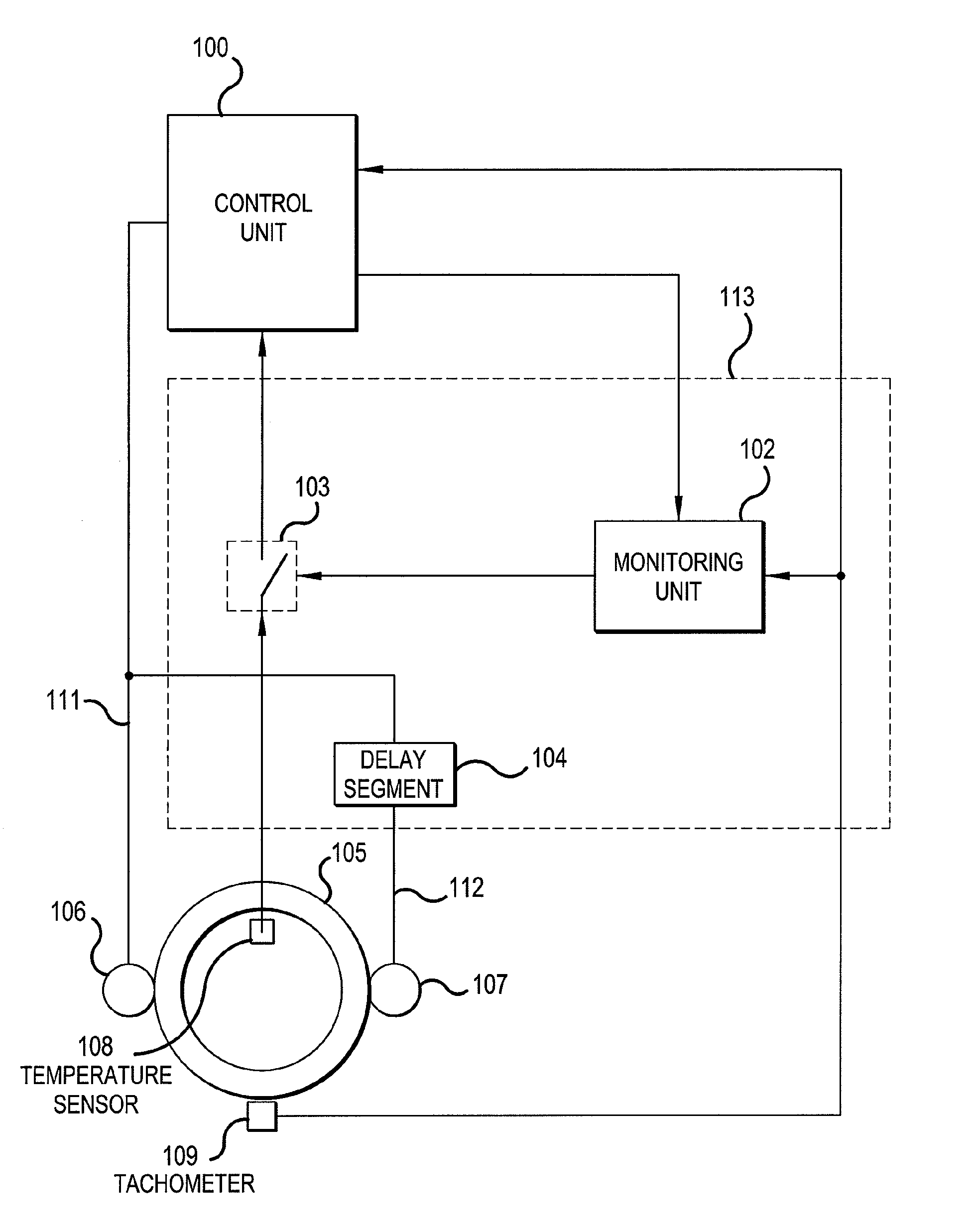
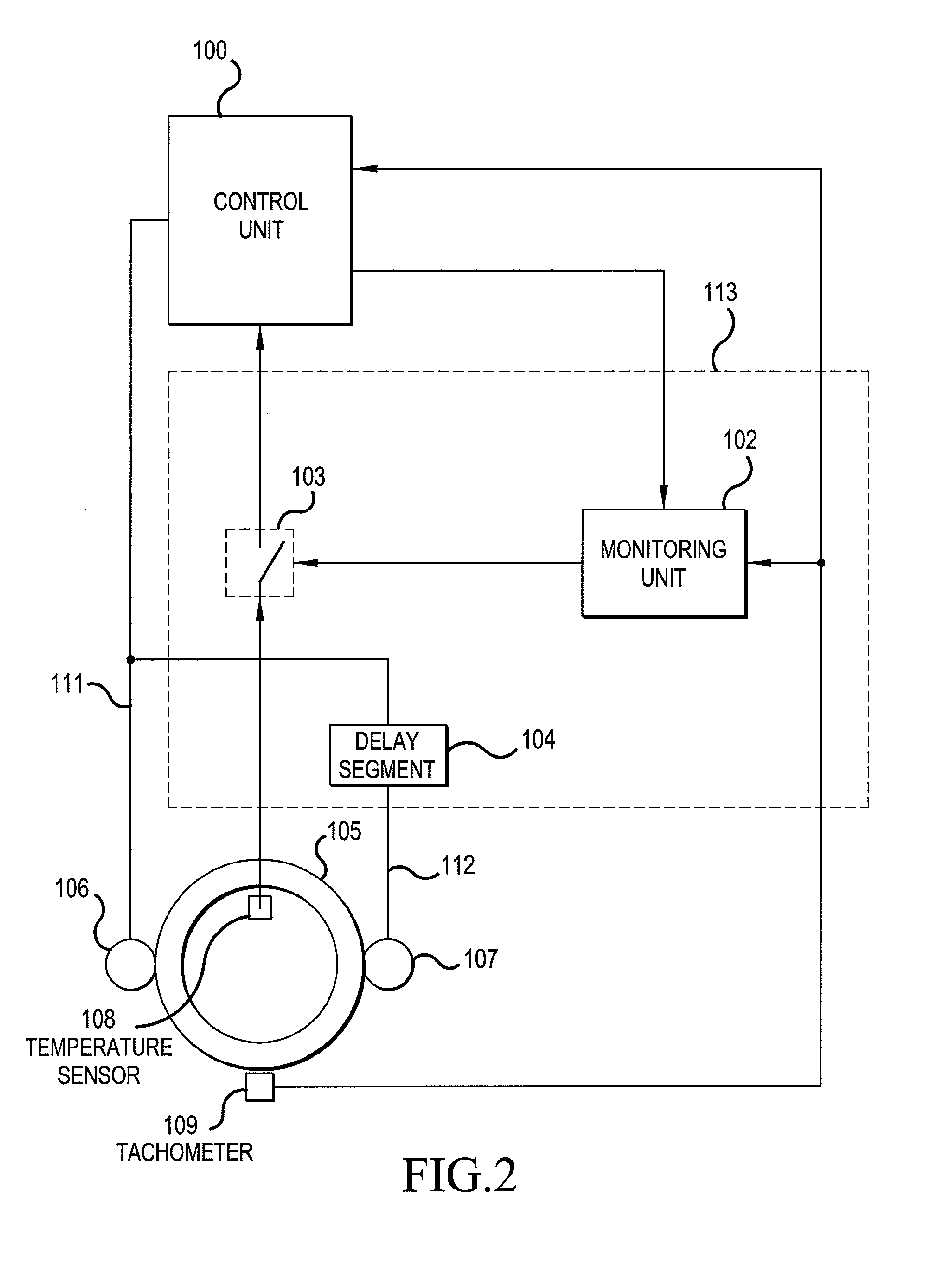
[0023]The invention pertains to the improvement of safety in an elevator system, which comprises at least one elevator car, elevator ropes, an elevator motor, a traction sheave and at least two holding brakes per elevator car. With the invention the operating safety of elevators can be improved in a situation in which the friction coefficient between the brake shoe and the brake drum of the holding brake is reduced owing to wear of the brake or owing to some other reason. A contaminating substance such as oil or dirt can find its way onto the braking surface, or the brakes can be incorrectly adjusted. The invention also presents a new elevator system that is better in terms of operating safety than prior-art.

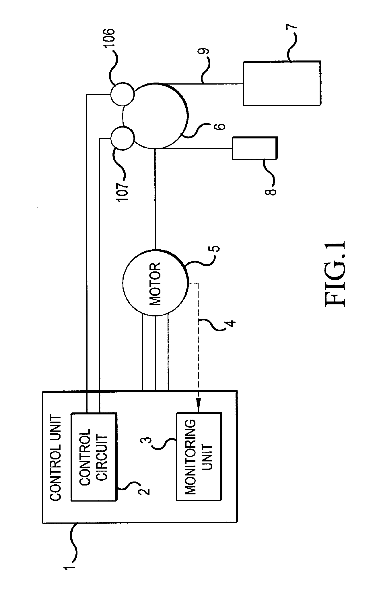
[0024]FIG. 1 presents an elevator system according to the invention. The elevator car 7 can be moved in the elevator shaft (not shown in the figure) in the desired manner via the elevator motor 5, the traction sheave 6 and the elevator ropes 9. The elevator system according to F...


PUM


Abstract

In the invention a method is presented for ensuring operating safety in an elevator system, an elevator system, and a safety device of an elevator system. The elevator system includes at least an elevator car, elevator ropes, an elevator motor, a traction sheave and at least two holding brakes, which holding brakes are arranged to prevent movement of the elevator car when the elevator is stopped. According to the invention the first holding brake is engaged at the end of an elevator run, and the other holding brakes are engaged with a delay. When one holding brake is engaged, the state of motion of the elevator and any slipping of the brake is monitored. If the brake is detected as slipping, a procedure for preventing a hazardous situation is performed.

Description

[0001]This application is a Continuation of copending PCT International Application No. PCT / FI2006 / 000278 filed on Aug. 16, 2006, which designated the United States, and on which priority is claimed under 35 U.S.C. § 120. This application also claims priority under 35 U.S.C. § 119(a) on Patent Application Ser. No(s). FI 20050840 filed in Finland on Aug. 19, 2005. The entire contents of each of the above documents is hereby incorporated by reference.FIELD OF THE INVENTION[0002]The present invention relates to a method as defined in the preamble of claim 1 for ensuring the operating safety of an elevator, an elevator system as defined in the preamble to claim 5 and a safety device as defined in the preamble of claim 9 for improving operating safety in an elevator system.BACKGROUND OF THE INVENTION[0003]In the mechanical control of the travel of the elevator cars of an elevator system, motors, brakes and a control system to control them are needed. The driving force from the motor trav...

Claims


Application Information

Patent Timeline
Patent Type & Authority Patents(United States)
IPC IPC(8): B66B1/34B66BB66B5/00
CPCB66B5/0031B66B5/02
Inventor OSTERMAN, JARISUUR-ASKOLA, SEPPOMYLLYNEN, JARMOMAKIMATTILA, SIMOKORPELA, JUKKAKIISKI, JONI
Owner KONE CORP
Why Eureka
Try Eureka