Adjustable electrical box and flange member for installation on a brick or stone wall

a technology of electrical boxes and flanges, which is applied in the direction of machine supports, coupling device connections, mechanical equipment, etc., can solve the problems of unsightly mortar area around the electrical box, difficulty in using a conventional electrical box, and inconvenient use of conventional electrical boxes

Active Publication Date: 2009-05-05
ARLINGTON INDS
View PDF11 Cites 19 Cited by
  • Summary
  • Abstract
  • Description
  • Claims
  • Application Information

AI Technical Summary

Problems solved by technology

Brick and stone however are provided in a range of thicknesses, which makes it difficult to use a conventional electrical box.
As a result, conventional electrical boxes may not be appropriate for buildings constructed of wide bricks or stones.
The conventional electrical box could be mortared into a hole in the brick or stone wall, but this typically creates an unsightly area of mortar around the electrical box.

Method used


Image

  • Adjustable electrical box and flange member for installation on a brick or stone wall
  • Adjustable electrical box and flange member for installation on a brick or stone wall
  • Adjustable electrical box and flange member for installation on a brick or stone wall

Examples


Embodiment Construction

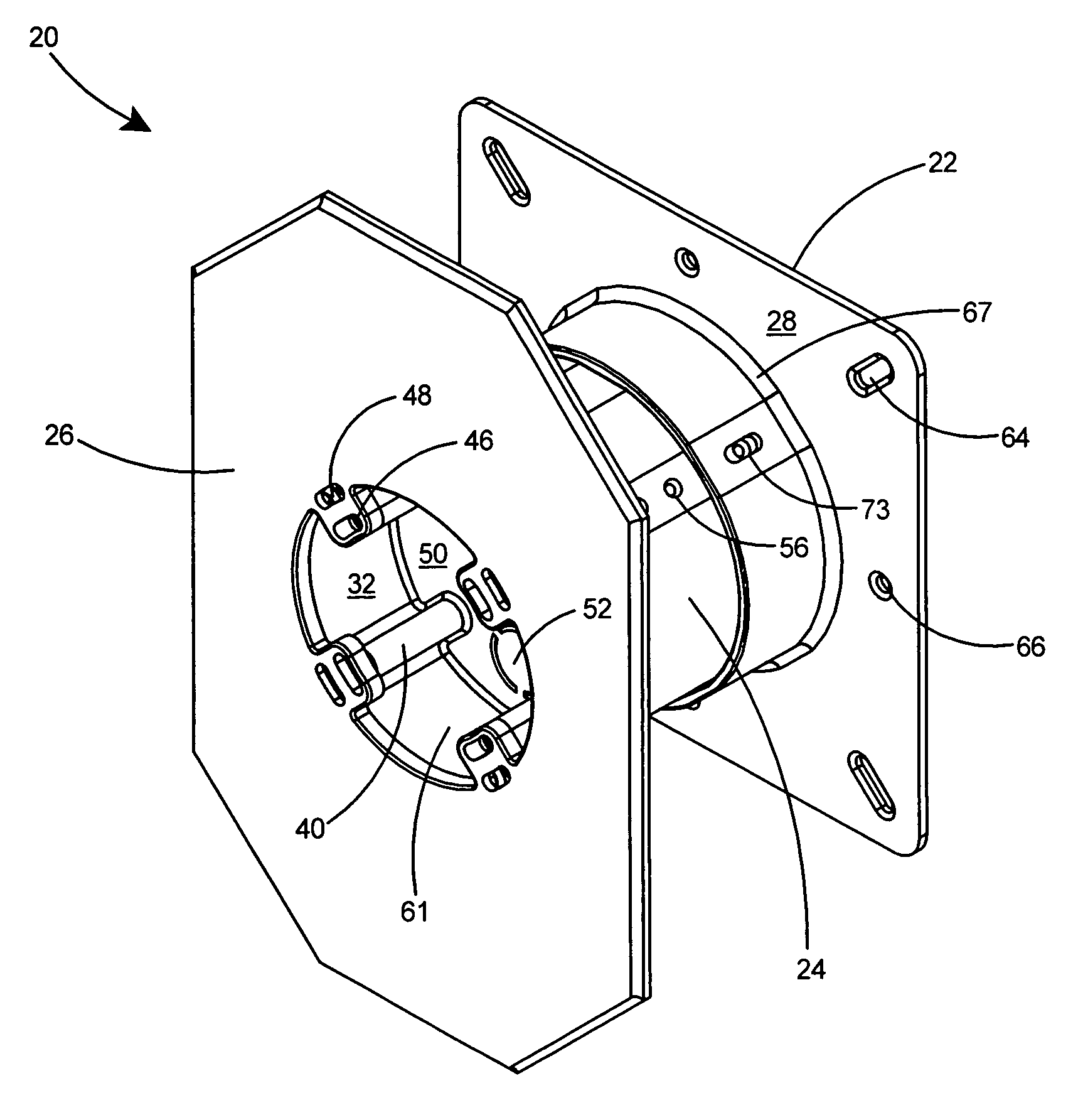
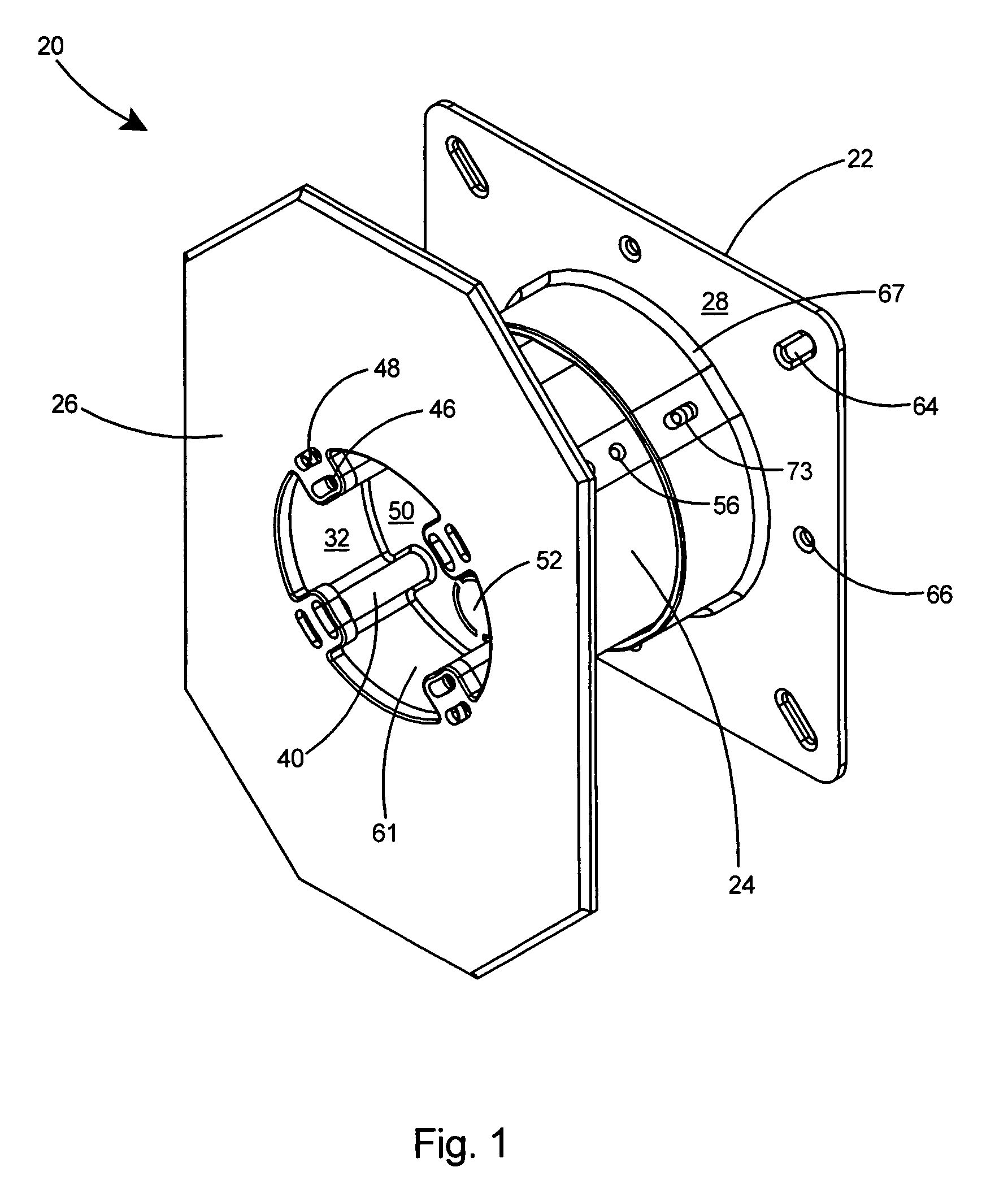
[0026]With reference to the preferred embodiment of FIG. 1, the present invention is an adjustable electrical box assembly 20 including a flange member 22, an electrical box 24, and a faceplate 26. The adjustable electrical box assembly 20 simplifies the process of installing an electrical fixture on a brick or stone wall. Bricks and stones are supplied in various widths or thicknesses and the adjustable electrical box assembly of the present invention enables an installer to rapidly adjust the assembly 20 to accommodate bricks or stones of a wide variety of thicknesses.

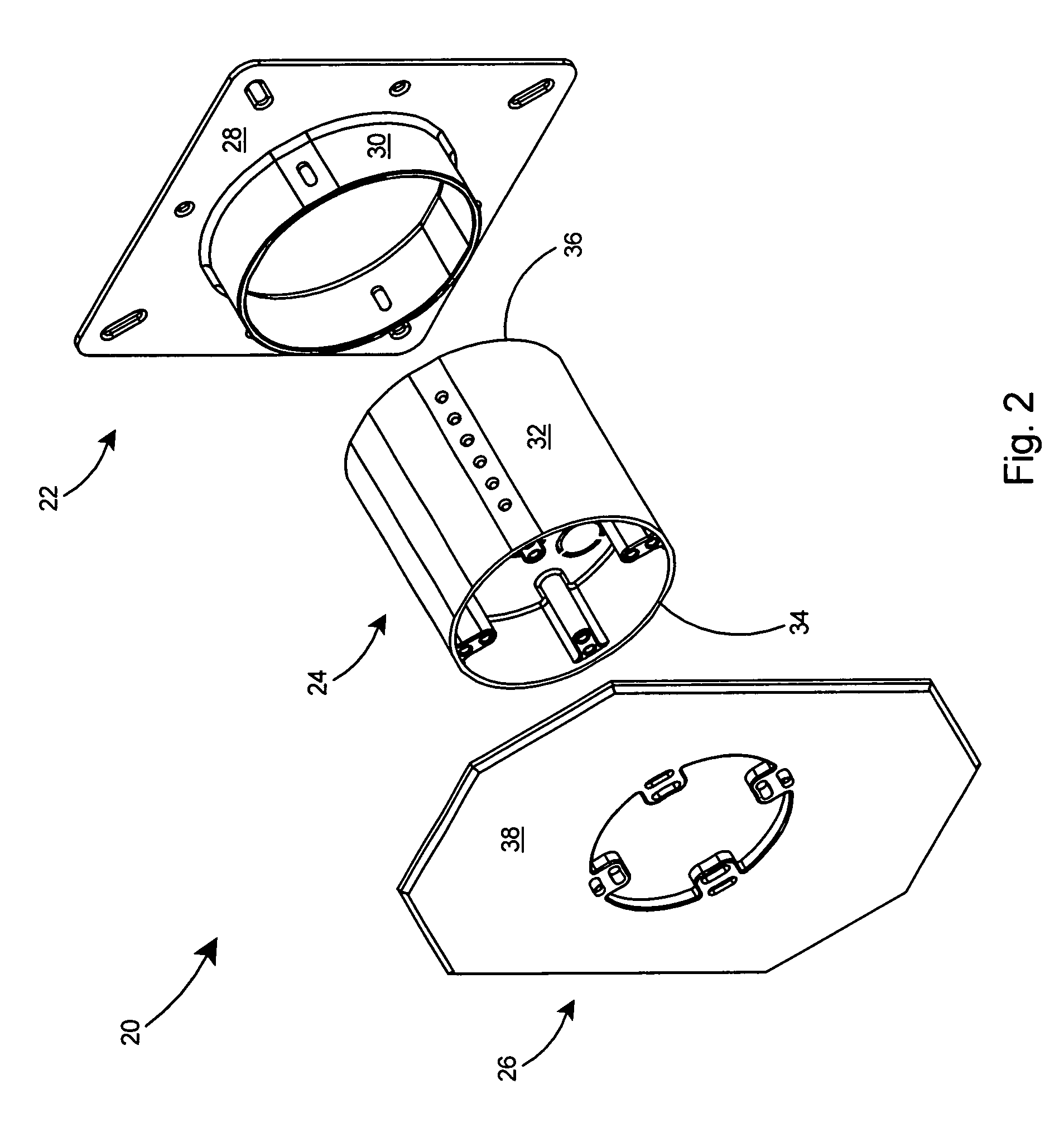
[0027]Referring to FIG. 2, the flange member 22 includes a flange 28 and a forward extending collar 30. The electrical box 24 includes sidewalls 32 having a front edge 34 and a rear edge 36. The sidewalls 32 of the electrical box 24 are telescopically received in the collar 30 of the flange member 22. The faceplate 26 portion of the adjustable electrical box assembly 20 includes a front panel 38 that is secured at th...


PUM


Abstract

An adjustable electrical box assembly for providing electrical service on a brick or stone wall. The assembly includes a flange member, box member, and a faceplate. The flange member includes a flange and a forward extending collar. The electrical box includes sidewalls that are telescopically received in the collar of the flange member and a fastening arrangement for securing the electrical box to the flange member. After installing an electrical fixture within the electrical box, a faceplate is secured to the front of the box member.

Description

FIELD OF THE INVENTION[0001]This invention relates to electrical junction boxes and specifically to an adjustable electrical box assembly that enables mounting an electrical fixture to a brick or stone wall.BACKGROUND OF THE INVENTION[0002]Conventional electrical boxes are commonly used when installing electrical fixtures on a brick or stone building. During building construction, the conventional electrical box is mounted to the substrate with screws, nails, or similar fasteners. For a successful installation, the sidewalls of the conventional electrical box must extend through the brick or stone.[0003]Brick and stone however are provided in a range of thicknesses, which makes it difficult to use a conventional electrical box. The conventional electrical box, having sidewalls of a fixed length, may not be long enough to extend from the substrate through the brick or stone layer. As a result, conventional electrical boxes may not be appropriate for buildings constructed of wide bric...

Claims


Application Information

Patent Timeline
Patent Type & Authority Patents(United States)
IPC IPC(8): H01H9/02
CPCH02G3/121Y10S248/906
Inventor GRETZ, THOMAS J.
Owner ARLINGTON INDS
Why Eureka
Try Eureka