Placement information estimating method and information processing device

a technology of information processing device and placement information, which is applied in the field of placement information estimating method and information processing device, can solve the problems of inability to obtain accurate placement information of markers, obtained simultaneously,

Inactive Publication Date: 2009-05-05
CANON KK
View PDF11 Cites 45 Cited by
  • Summary
  • Abstract
  • Description
  • Claims
  • Application Information

AI Technical Summary

Benefits of technology

[0021]The present invention has been made in light of the aforementioned problems, and provides a method for obtaining the placement information of various types of markers accurately by photographing scenes including markers using an imaging device and obtaining the placement information of multiple types of markers, of which the placement information has different amounts of information, simultaneously.
[0022]Also, the present invention provides a method for obtaining the placement information of various types of markers accurately by photographing scenes including markers, using an imaging device, and repeatedly obtaining the placement information of multiple types of markers, of which the placement information has different amount of information, in an alternating manner.
[0025]According to the first aspect of the present invention, the placement information of various types of markers can be obtained accurately by photographing scenes including markers using an imaging device and obtaining the placement information of multiple types of markers, of which the placement information has different amounts of information, simultaneously.
[0026]Also, according to the second aspect of the present invention, the placement information of various types of markers can be obtained accurately by giving heavier weight to markers having higher reliability of detected results from an image to obtain the placement information.
[0027]Also, according to a third aspect of the present invention, the placement information of various types of markers can be obtained accurately by photographing scenes including markers using an imaging device and repeatedly obtaining the placement information of multiple types of markers, of which the placement information has different amounts of information, one after the other.

Problems solved by technology

The registration problem in the AR technology corresponds to a problem of obtaining the position and orientation of an imaging device in a scene (i.e., in the reference coordinate system) in the case of the video see-through method.
Similarly, in the case of the optical see-through method, the registration problem corresponds to a problem for obtaining the position and orientation of an observer or a display device in the scene.
With the aforementioned conventional methods for measuring the position and orientation of a marker, the position of a point marker, and the position and orientation of a “planar” marker such as a square marker cannot be obtained simultaneously.
Accordingly, even if different types of marker (point marker and plane marker, for example) had been photographed on the same image, the placement information of each type of marker, and the position and orientation of an imaging device so as to minimize the projection error cannot be obtained, so the placement information of the markers cannot be obtained accurately.

Method used


Image

  • Placement information estimating method and information processing device
  • Placement information estimating method and information processing device
  • Placement information estimating method and information processing device

Examples


first embodiment

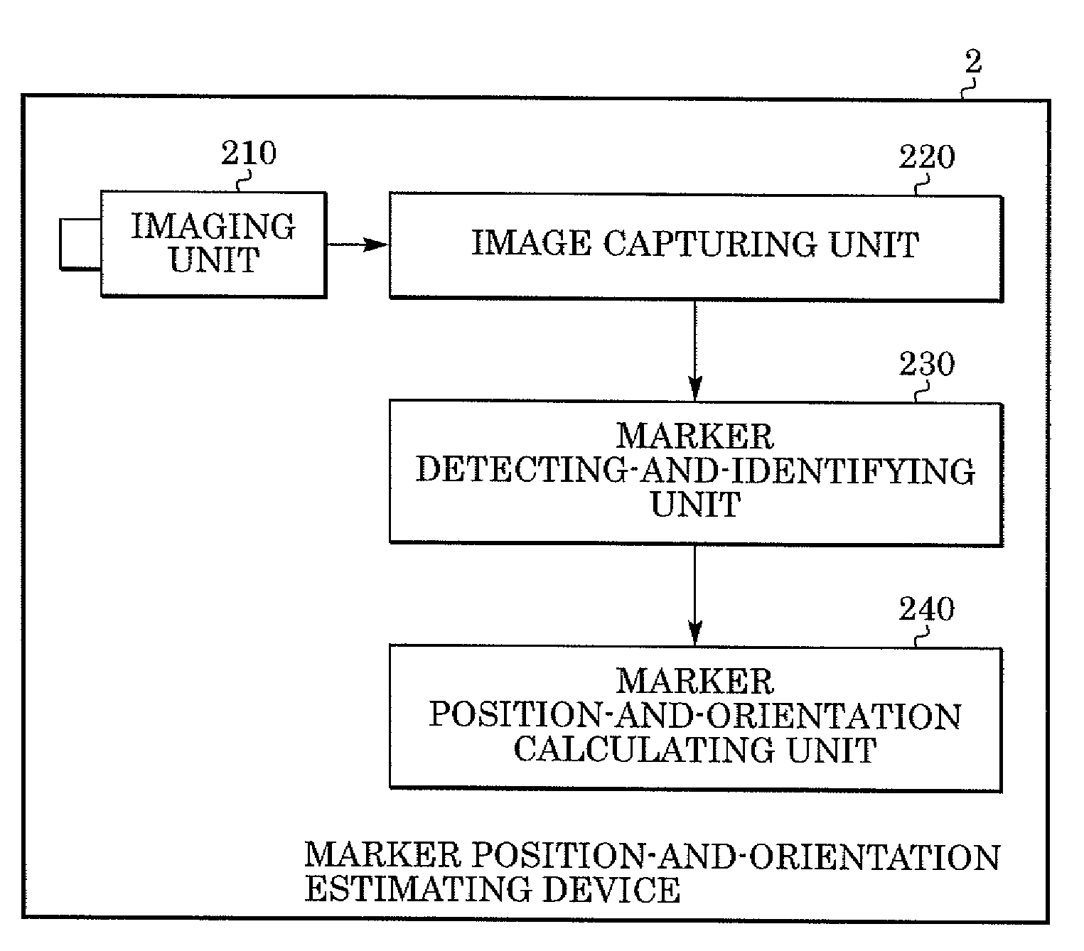
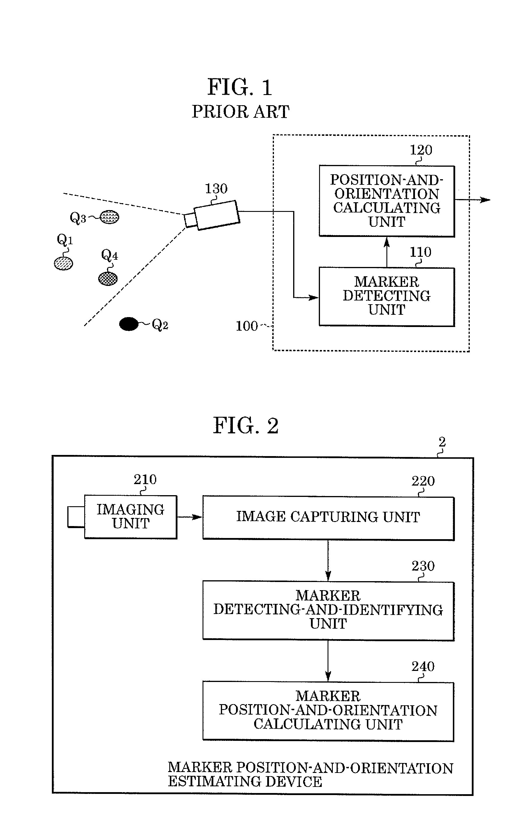
[0045]FIG. 2 is a block diagram illustrating the functional configuration of a marker position-and-orientation estimating device 2 according to the present embodiment. An imaging unit 210 is a camera, which photographs a scene in which markers are disposed. An image capturing unit 220 inputs an image photographed by the imaging unit 210 to a computer. A marker detecting-and-identifying unit 230 detects markers from the image input to the computer from the image capturing unit 220, and identifies each detected marker. A marker position-and-orientation calculating unit 240 calculates the position and orientation of each marker based on the marker detection results of the marker detecting-and-identifying unit 230.

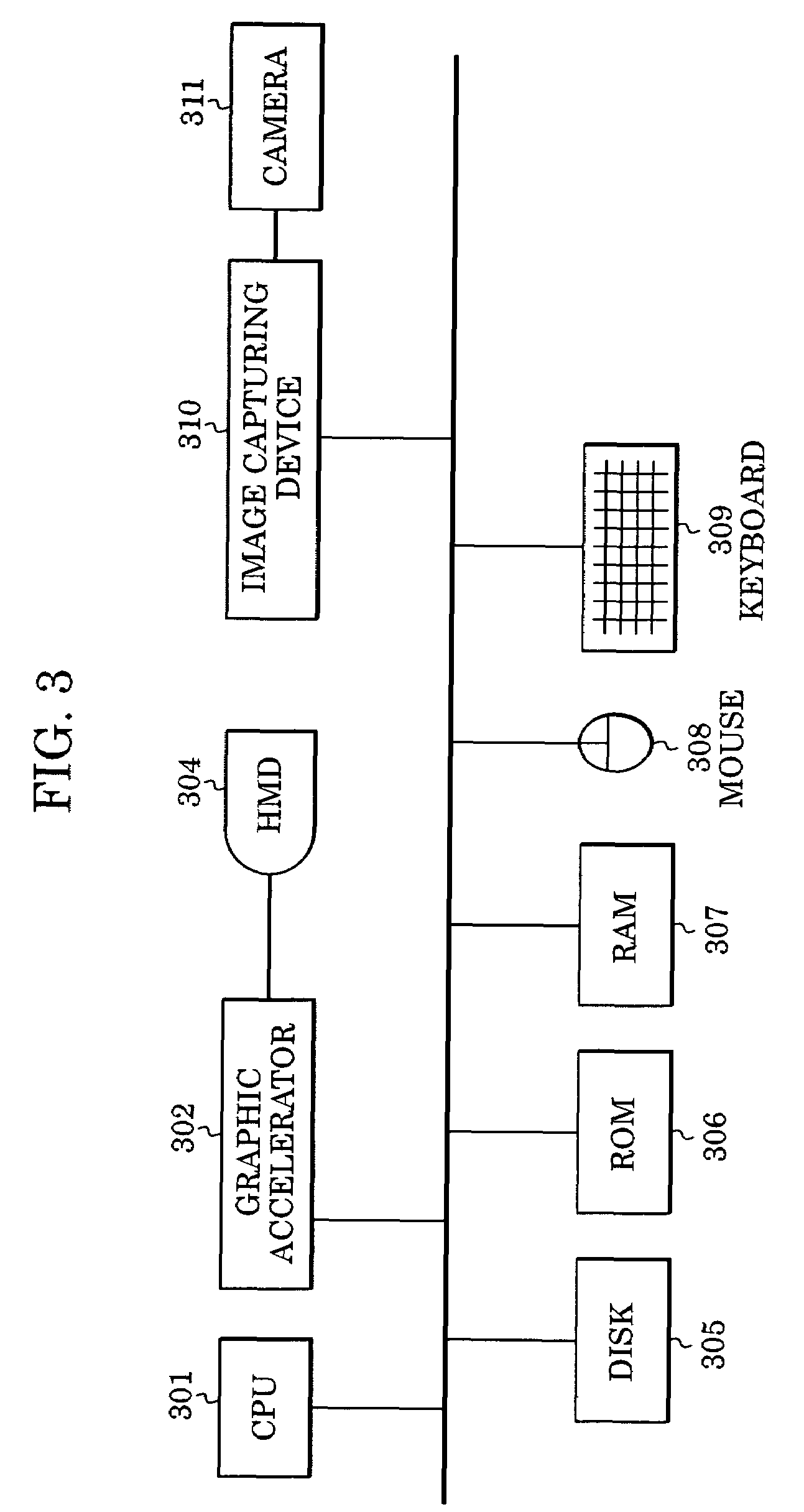
[0046]FIG. 3 is a block diagram illustrating the hardware configuration of the marker position-and-orientation estimating device 2 according to the present embodiment. The hardware configuration illustrated in FIG. 3 is the same configuration as that of a common personal compu...

second embodiment

[0118]With the first embodiment, the projection error (a sum of error between the calculated position of the projected position and the observed position) regarding point markers and the projection error of square markers are subjected to the least mean square method simultaneously by obtaining correction values regarding the positions of the point markers, and the positions and orientations of the square markers simultaneously, thus obtaining the positions of the point markers and the positions and orientations of the square markers accurately. With the second embodiment, the positions of point markers and the positions and orientations of square markers are obtained accurately by alternately repeating obtaining the positions of the point markers, and the positions and orientations of the square markers.

[0119]FIG. 10 is a flowchart illustrating procedures for obtaining the positions of point markers, and the positions and orientations of square markers according to the second embod...

third embodiment

[0131]With the first and second embodiments, estimation of the positions and orientations of markers have been performed following the images of scenes including markers being photographed with the imaging device. With the third embodiment, estimation is performed based on the images stored in the storage device beforehand, thus performing offline processing.

[0132]FIG. 11 is a block diagram illustrating the functional configuration of a marker position-and-orientation estimating device 3 according to the third embodiment. The marker position-and-orientation estimating device 3 includes an image storing unit 350, image capturing unit 320, marker detecting-and-identifying unit 330, and marker position-and-orientation calculating unit 340. Description is made below regarding the procedures of marker position-and-orientation estimation in the marker position-and-orientation estimating device 3.

(1. Capturing of Images)

[0133]N images of scenes including markers are photographed beforehand...


PUM


Abstract

A method is provided for estimating the placement information of a plurality of types of markers of which the amounts of the placement information differ respectively, detects a plurality of types of markers from multiple images, calculates the position where the detected marker is projected on an image surface based on the approximate values of the positions and orientations of an imaging device when multiple images are photographed, obtains the correction value of the placement information of a marker so as to reduce a sum of error between the position of the detected marker on the image surface and the projected position of the marker calculated, corrects the placement information of the marker, and also calculates the placement information of a plurality of types of markers by repeating these processes.

Description

BACKGROUND OF THE INVENTION[0001]1. Field of the Invention[0002]The present invention relates to a method for estimating the placement information of markers disposed within a 3-D space.[0003]2. Description of the Related Art[0004]In recent years, studies regarding MR (Mixed Reality) technology have been actively pursued. The MR technology is used for seamlessly integrating real space with virtual space created by a computer. Of the MR technology, AR (Augmented Reality; also referred to as enhanced reality) technology which superimposes virtual space over real space has particularly attracted attention.[0005]An image display device on which the AR technology displays an image is realized by a video see-through method which displays a synthesized image obtained by superimposing a computer-generated image concerned with virtual space (a virtual object, character information, or the like, drawn with computer graphics) rendered according to the position and orientation of a later-descri...

Claims


Application Information

Patent Timeline
Patent Type & Authority Patents(United States)
IPC IPC(8): G06K9/00G01B11/00G01B11/26G06T7/00G06T7/60G06V10/24
CPCG06K9/32G06T7/0042G06K2009/3225G06T7/73G06V10/24G06V10/245
Inventor KOTAKE, DAISUKEUCHIYAMA, SHINJI
Owner CANON KK
Why Eureka
Try Eureka