Adaptive power amplifier linearization in time division duplex communication systems

Active Publication Date: 2009-05-05
REDSTONE LOGICS LLC
View PDF2 Cites 34 Cited by
  • Summary
  • Abstract
  • Description
  • Claims
  • Application Information

AI Technical Summary

Problems solved by technology

While there are benefits to adaptive power amplifier linearization, there are also problems associated therewith.

Method used


Image

  • Adaptive power amplifier linearization in time division duplex communication systems
  • Adaptive power amplifier linearization in time division duplex communication systems
  • Adaptive power amplifier linearization in time division duplex communication systems

Examples


Embodiment Construction

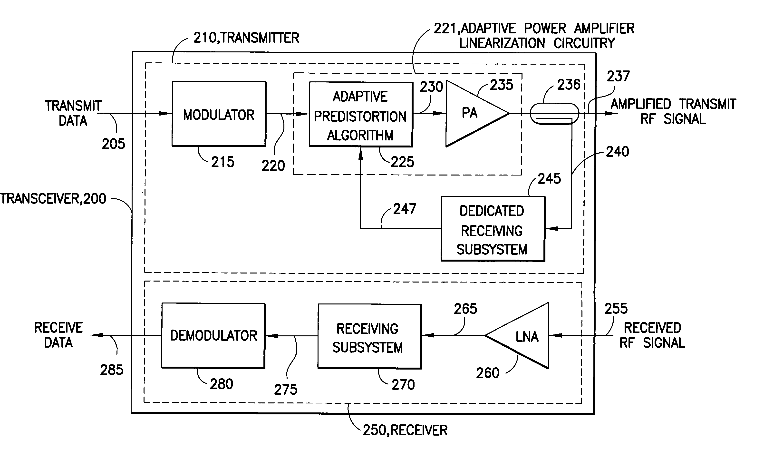
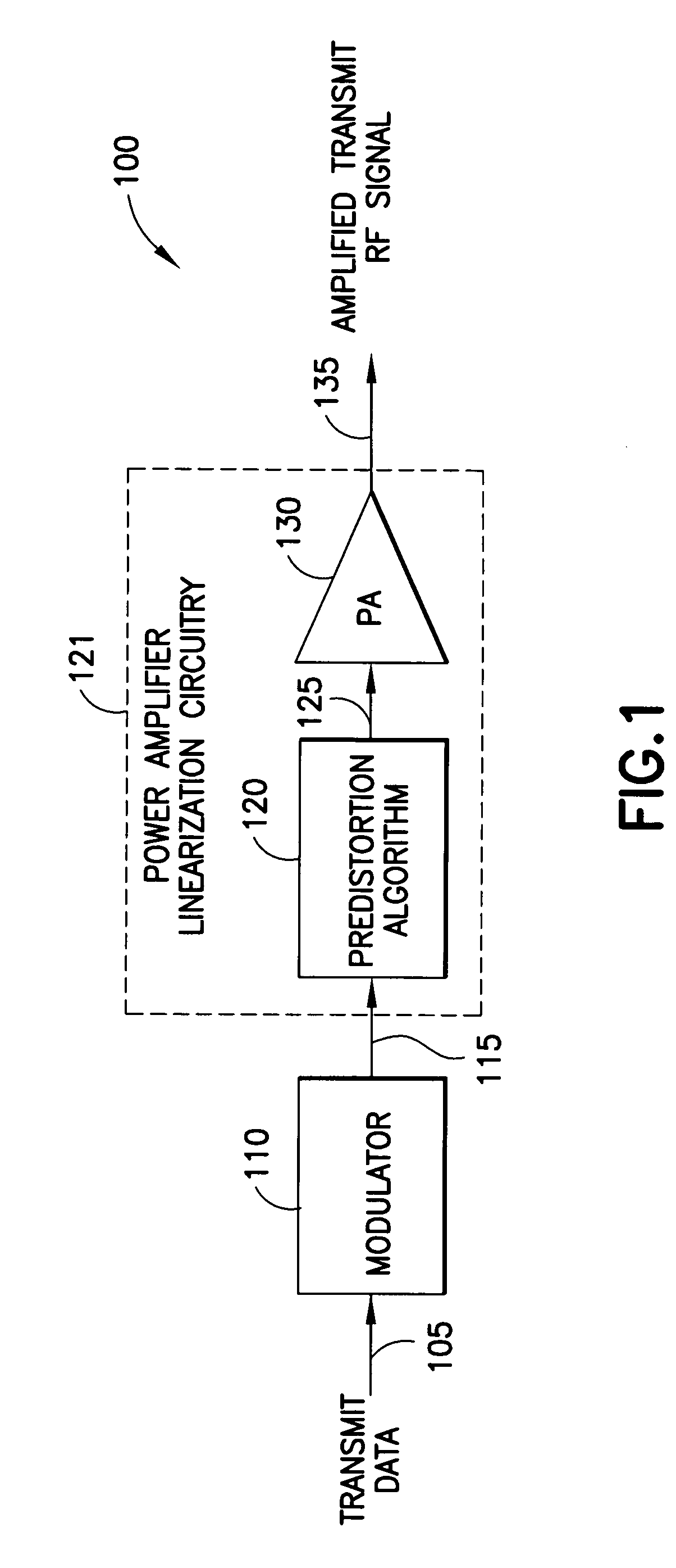
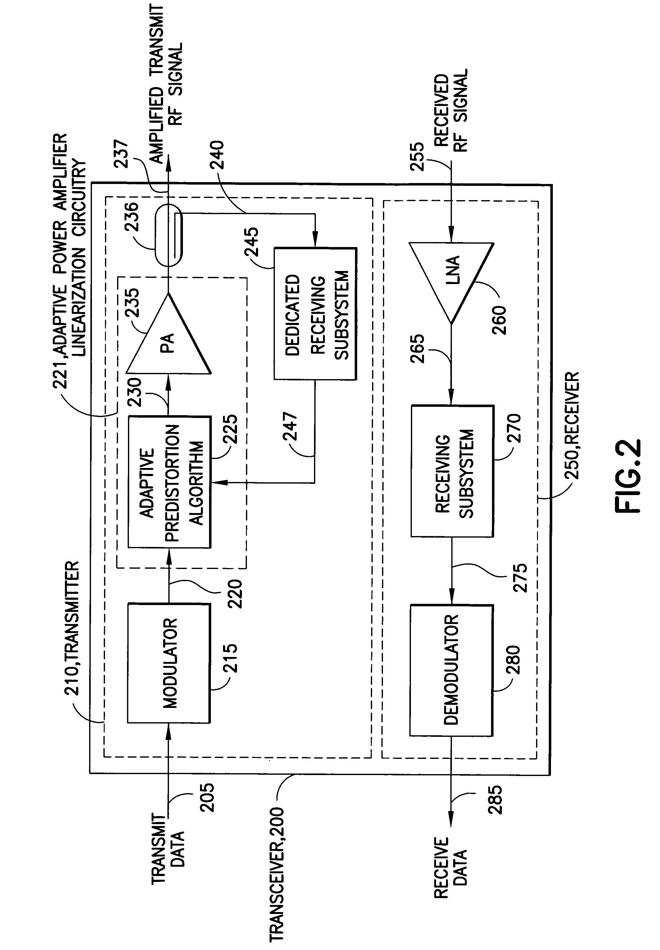
[0014]As previously described, power amplifier linearization is one technique used to reduce the effects of nonlinear characteristics of power amplifiers. Shown in FIG. 1 is a transmitter 100 that comprises a modulator 110 coupled to power amplifier linearization circuitry 121. The power amplifier linearization circuitry 121 comprises predistortion algorithm circuitry 120 and a power amplifier 130. The modulator 110 modulates transmit data 105 through techniques such as linear pulse shaped modulation. The modulator 110 produces a modulated data signal 115, which is coupled to the predistortion algorithm circuitry 120. It is to be noted that signals are coupled though circuitry such as traces on a circuit board or wiring levels on a semiconductor. A signal is therefore typically considered to be separate from the circuitry on which the signal is placed. For clarity, however, signals will mainly be described herein without regard to the circuitry on which the signal resides.

[0015]The ...


PUM


Abstract

In an aspect of the invention, a method is performed in a transceiver for adaptive power amplifier linearization in time division duplex communication systems. The method comprises, in response to a first condition, performing, using a feedback signal generated by receiving subsystem circuitry, adaptive power amplifier linearization on a signal to be transmitted. The method additionally comprises, in response to a second condition, performing operations in order to determine receive data from a received radio frequency (RF) signal. The operations use at least the receiving subsystem circuitry. In a further aspect of the present invention, a transceiver is disclosed.

Description

TECHNICAL FIELD[0001]This invention relates generally to radio frequency communication and, more specifically, relates to adaptive power amplifier linearization.BACKGROUND OF THE INVENTION[0002]Power amplifiers are used in certain communication systems to boost amplitude of a transmitted signal to allow reliable reception by a distant receiver. All power amplifiers exhibit some nonlinear characteristics, and the nonlinear characteristics may be described by quantifying properties of AM / AM and AM / PM curves for the power amplifier. An AM / AM curve represents input amplitude to output amplitude conversion, while the AM / PM curve represents input amplitude to output phase conversion. Nonlinearities caused by the nonlinear characteristics of power amplifiers distort the spectrum of the transmitted signal, causing the bandwidth of the output signal of the power amplifier to be wider than the bandwidth of the input signal of the power amplifier. Consequently, some form of compensation techni...

Claims


Application Information

Patent Timeline
Patent Type & Authority Patents(United States)
IPC IPC(8): H04B1/04
CPCH03F1/3247H03F3/24H03F2200/204H03F2200/207H04B2001/0433H03F1/34
Inventor GIALLORENZI, THOMAS R.RICE, MICHAELMCINTIRE, WILLIAM K.SUN, JUNE
Owner REDSTONE LOGICS LLC
Why Eureka
Try Eureka