Locking aerosol dispenser

a dispenser and aerosol technology, applied in the field of aerosol dispensers, can solve the problems of requiring more force than desirable for the user, requiring more force than desirable to operate, and overly complex design molds, etc., and achieves the effects of simple structure, convenient operation, and convenient molded and assembled

Active Publication Date: 2009-05-12
PRECISION VALVE CORP
View PDF64 Cites 31 Cited by
  • Summary
  • Abstract
  • Description
  • Claims
  • Application Information

AI Technical Summary

Benefits of technology

[0003]The present invention is intended to provide a locking aerosol dispenser that is robust in its construction, easily molded and assembled, easy to operate between its inoperative and operative positions, easy to actuate, and functions reliably and efficiently.
[0005]A dome member that is not intended to be rotatable in operation extends above the base lock member, attaches to the mounting cup, attaches to the base lock member, and captures the base lock member between the dome and product container. The dome member further includes a product channel member that is connected to the dome member by a thermoplastic elastomeric button member molded over an opening at the top of the dome, over dome surfaces adjacent the opening, and over the product channel. The product channel at its opposite end connects to the valve stem. The product channel moves easily up and down due to the resiliency of the button member.
[0007]The mounting cup is directly adjacent to and supports the bridge member against excessive downward pressure due to top-loading on the top button when the actuator is in its off-locked position. Damage to the dispenser is thereby avoided.

Problems solved by technology

Some of these designs are overly complex to mold, while others require more force than desirable for the user to operate between the inoperative and operative positions.
Still other designs require more force than desirable to actuate the aerosol valve.
Further designs have created leaking problems.
Additional designs are not sufficiently robust and are vulnerable to damage to their parts and operation due to excessive top loads from misuse, handling, shipping, etc.

Method used


Image

  • Locking aerosol dispenser
  • Locking aerosol dispenser
  • Locking aerosol dispenser

Examples


Embodiment Construction

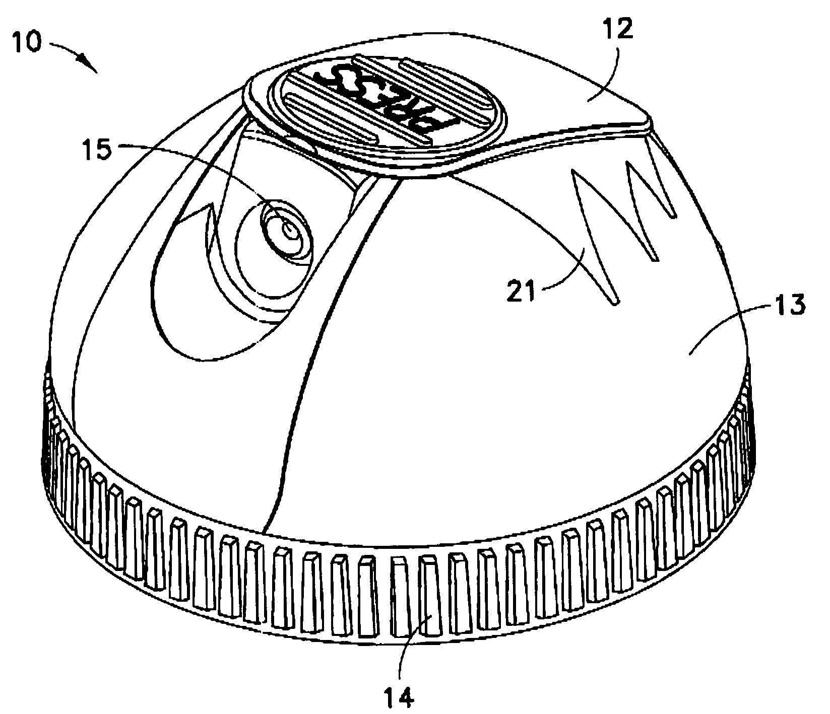
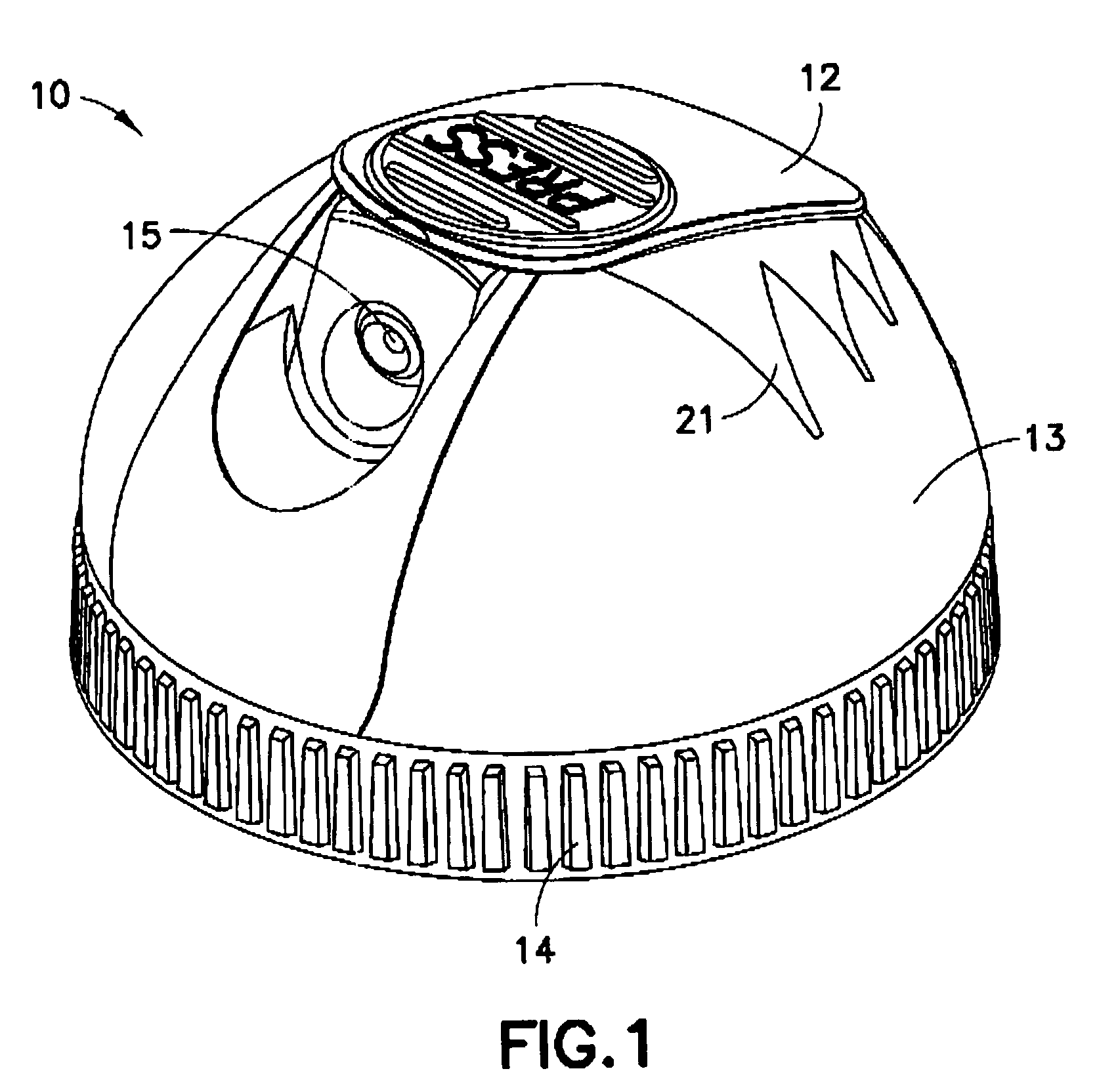
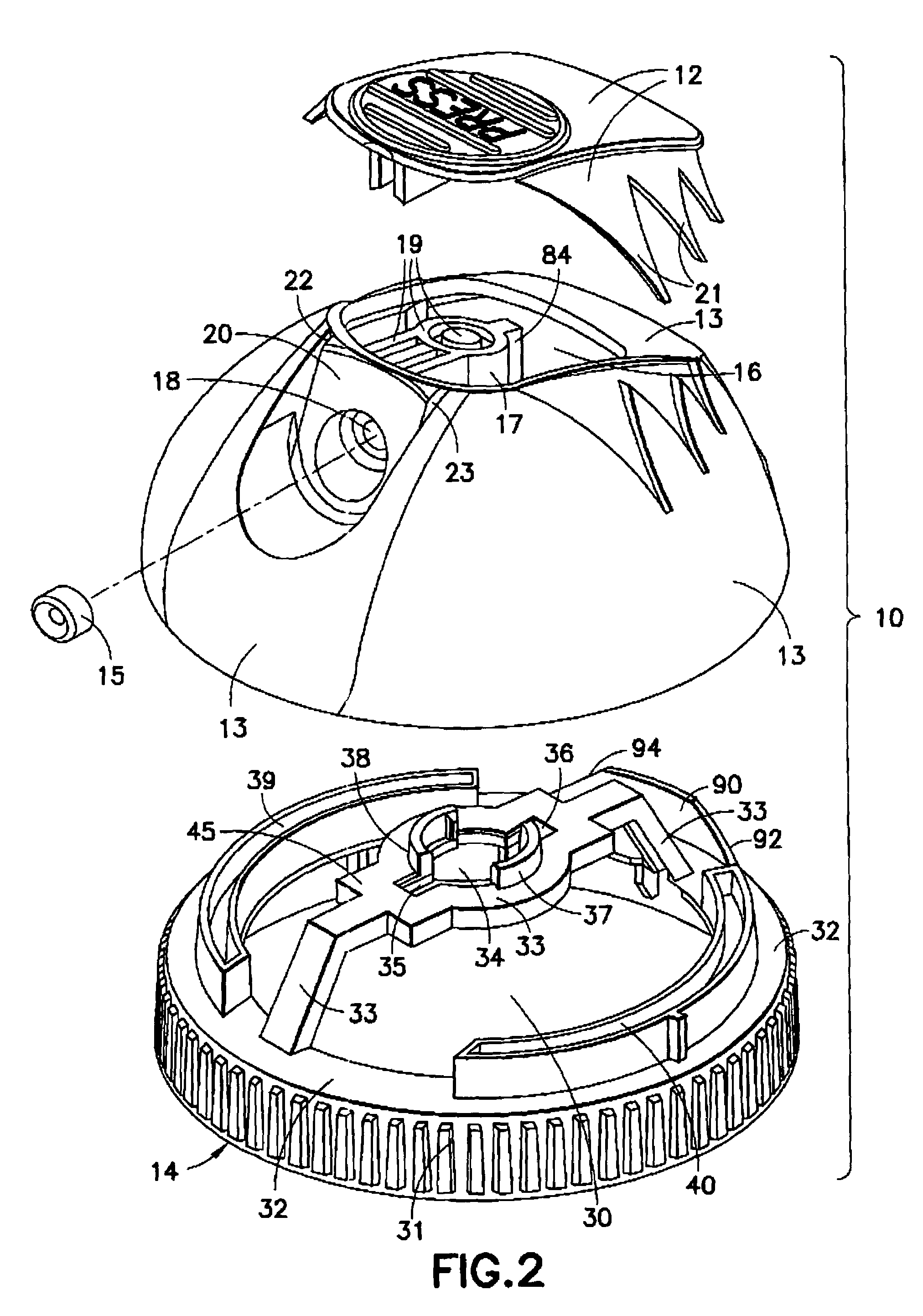
[0023]Referring to FIGS. 1, 3 and 6, locking aerosol dispenser 10 of the present invention is illustrated as assembled, with FIGS. 3 and 6 showing dispenser 10 mounted on the top of aerosol product container 11. FIG. 2 is an exploded view of locking aerosol dispenser 10, illustrating top button member 12, dome member 13, base lock member 14 and nozzle insert member 15. When the assembled aerosol dispenser 10 is mounted on the aerosol container 11, rotatable base lock member 14 can be rotated between a locking position and an unlocking position with respect to non-rotatable dome member 13 as hereinafter described. Only when the dispenser 10 is unlocked can product be dispensed from container 11.

[0024]Dome member 13 includes a top opening 16 before top button member 12 is applied as hereinafter described, and further includes product channel member 17 which extends upwardly inside dome member 13 towards its top and then outwardly in dome member 13 to nozzle 18. The product channel mem...


PUM


Abstract

A locking aerosol dispenser with a dome, a top thermoplastic elastomeric button member molded over a dome opening, and a base lock member. The rotatable base lock rotates from locked to unlocked position with respect to the essentially non-rotatable dome. A product channel member in the dome is held by the elastomeric button, and not otherwise attached to the dome. The base lock has an upstanding bridge with unlocking slots within which extend fingers on the product channel member when the dispenser is unlocked and actuated. The base lock is not attached to the aerosol valve mounting cup. The dome is attached to the base lock member and the aerosol valve mounting cup, the dome capturing the base lock member between the dome and aerosol container.

Description

FIELD OF THE INVENTION[0001]The present invention relates to aerosol dispensers of the type often referred to as spray dome dispensers or actuators. More particularly, the present invention relates to such a dispenser having a top portion mounted on a bottom portion which is rotatable with respect to the top portion between a first operative position for valve actuation and a second inoperative position in which the valve cannot be actuated.BACKGROUND OF THE INVENTION[0002]Prior art locking aerosol dispensers have existed for many years and have had many different structural designs of interrelating parts. Some of these designs are overly complex to mold, while others require more force than desirable for the user to operate between the inoperative and operative positions. Still other designs require more force than desirable to actuate the aerosol valve. Further designs have created leaking problems. Additional designs are not sufficiently robust and are vulnerable to damage to the...

Claims


Application Information

Patent Timeline
Patent Type & Authority Patents(United States)
IPC IPC(8): B67B5/00B65D83/00B67D99/00
CPCB65D83/205B65D83/22B65D83/228
Inventor DOWNEY, MICHAEL PAULO'TOOLE, TIMOTHY
Owner PRECISION VALVE CORP
Why Eureka
Try Eureka