Hydrodynamic torque converter

a technology of torque converter and hydraulic pump, which is applied in the direction of fluid gearing, coupling, belt/chain/gearing, etc., can solve the problem of increasing the rotary force of the blades of the turbine wheel, and achieve the effect of less installation space and cost-effective production

Inactive Publication Date: 2009-05-19
LUK LAMELLEN & KUPPLUNGSBAU BETEILIGUNGS KG
View PDF9 Cites 1 Cited by
  • Summary
  • Abstract
  • Description
  • Claims
  • Application Information

AI Technical Summary

Benefits of technology

[0004]It is the object of the invention to create a hydrodynamic torque converter comprising a driving pump wheel, a driven turbine wheel and a guide wheel, which comprises guide wheel blades, wherein said hydrodynamic torque converter requires less installation space as compared to conventional torque converters and is producible cost-effectively.
[0005]The object is attained in a hydrodynamic torque converter comprising a driving pump wheel, a driven turbine wheel and a guide wheel, which comprises guide wheel blades, by attaching the guide wheel blades to the guide wheel such that they can move between a throughflow position and a guide position. In the guide position, a medium stream delivered from the pump wheel via the turbine wheel is supported against the guide wheel blades. This brings about a backpressure, which results in increasing the rotary force of the blades of the turbine wheel. The medium stream is guided from the guide wheel blades at an advantageous angle back to the blades of the pump wheel. If the pump wheel and the turbine wheel have approximately the same speed, then the direction of the medium stream changes such that it flows towards the guide wheel blades in another direction, for example, towards their rear side. Due to the incident flow from the other direction, the guide wheel blades move from their guide position into their throughflow position, in which they enable an unobstructed medium flow through the guide wheel. The rotatable bearing of the guide wheel and the freewheel can be omitted.
[0010]In another preferred embodiment of the torque converter, the guide wheel comprises an outer ring, which is connected to the flange using connecting webs. This increases the stability of the guide wheel.

Problems solved by technology

This brings about a backpressure, which results in increasing the rotary force of the blades of the turbine wheel.

Method used


Image

  • Hydrodynamic torque converter
  • Hydrodynamic torque converter
  • Hydrodynamic torque converter

Examples


Embodiment Construction

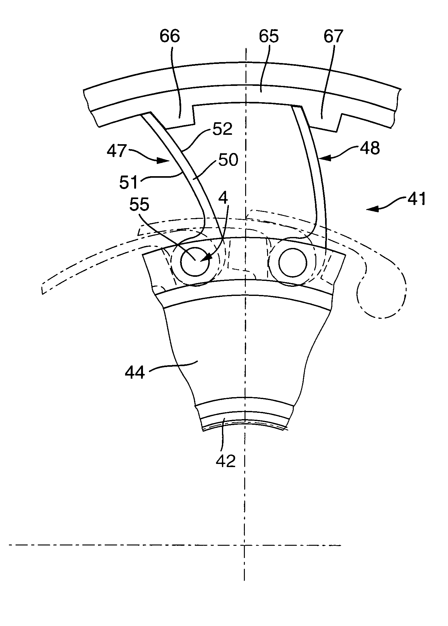
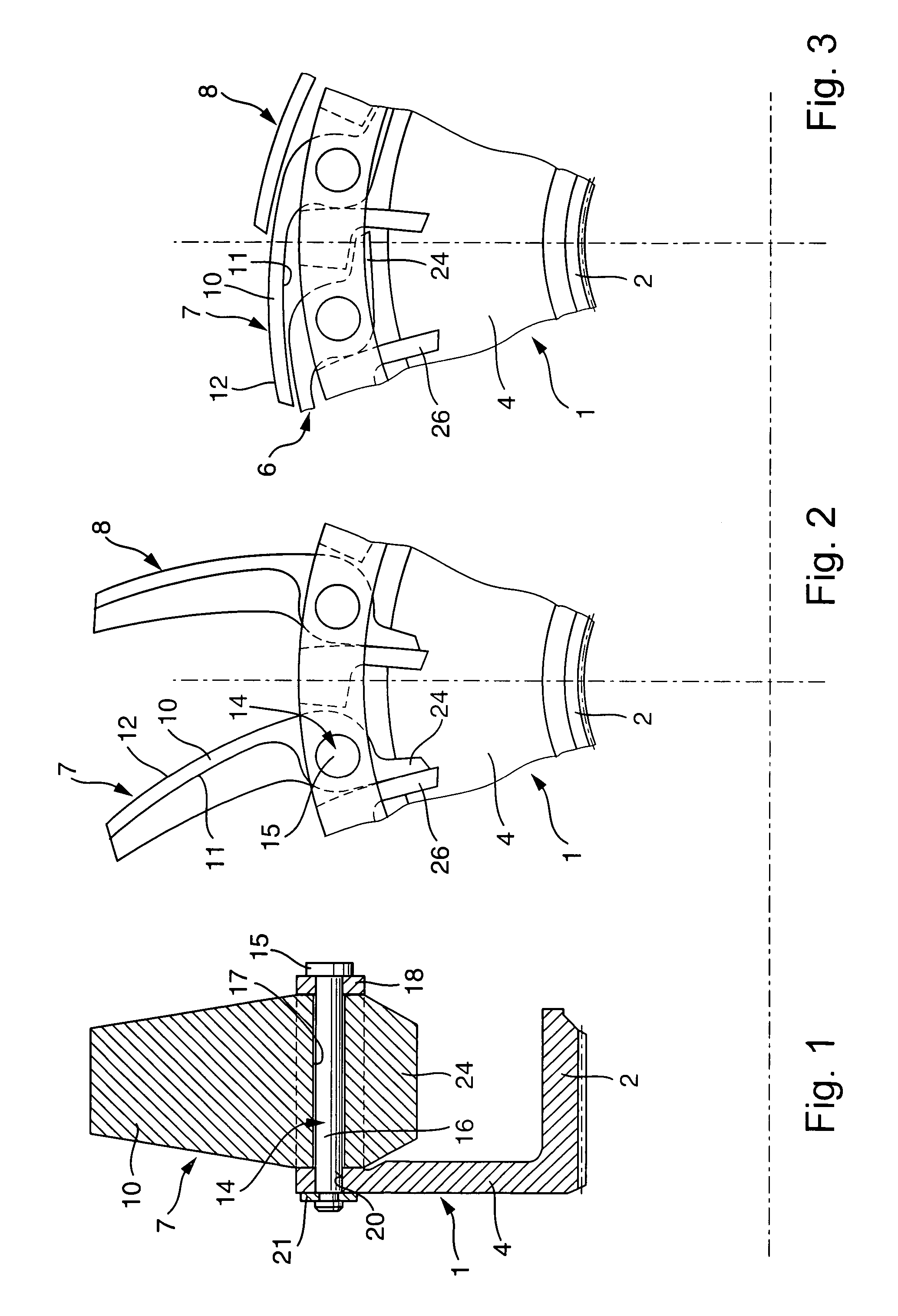
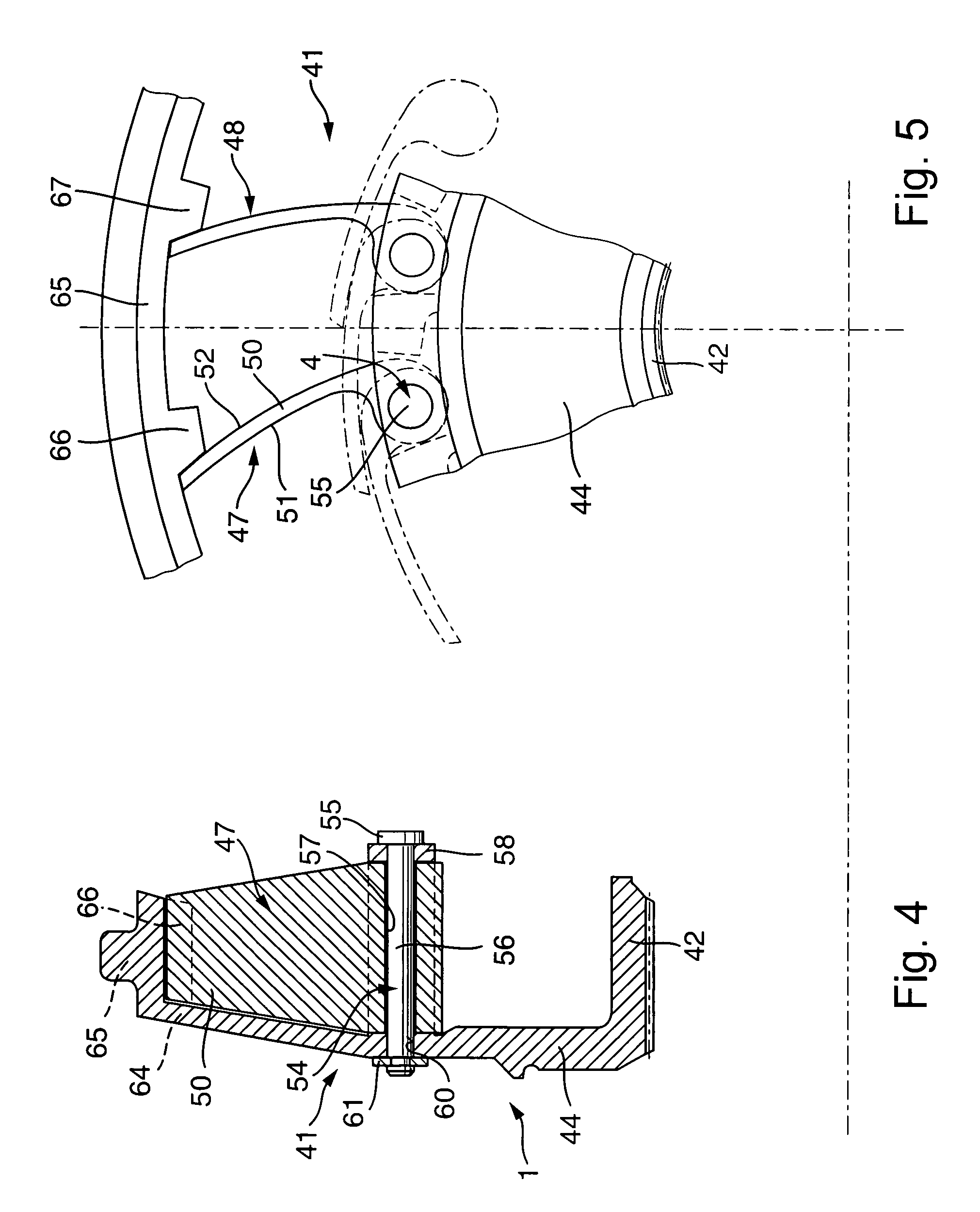
[0019]The invention relates to a hydrodynamic torque converter. The hydrodynamic torque converter is combined with a planetary gear in an automatic gearbox of a motor vehicle. It replaces a mechanical friction coupling as a starting clutch and expands, as a dynamic torque converter, the transmission ratio range of the planetary gear connected downstream. The hydrodynamic torque converter comprises a pump wheel driving at motor rotation speed, a driven turbine wheel, and a guide wheel. The pump wheel, turbine wheel, and the guide wheel are embodied as bent blade wheels and run in a closed housing filled with hydraulic oil.

[0020]FIGS. 1 to 3 illustrate a guide wheel 1 in different views and positions thereof. The guide wheel 1 comprises an inner ring 2, which substantially has the shape of a hollow circular cylinder. The inner ring 2 serves for fixing the guide wheel 1 to a suitable supporting structure. A flange 4 stretches radially outwards from the inner ring 2. Guide wheel blades ...


PUM


Abstract

The invention relates to a hydrodynamic torque converter comprising a driving pump wheel, a driven turbine wheel, and a guide wheel, which has guide wheel blades. In order to create a hydrodynamic torque converter, which requires less installation space than conventional torque converters and is producible cost-effectively, the guide wheel blades are attached to the guide wheel such that they can move between a throughflow position and a guide position.

Description

CROSS REFERENCE TO RELATED APPLICATIONS[0001]This patent application claims the benefit under 35 U.S.C. §119(e) of U.S. Provisional Application No. 60 / 689,756, filed Jun. 10, 2005, which application is incorporated herein by reference.FIELD OF THE INVENTION[0002]The invention relates to a hydrodynamic torque converter comprising a driving pump wheel, a driven turbine wheel, and a guide wheel, which comprises the guide wheel blades.BACKGROUND OF THE INVENTION[0003]In conventional hydrodynamic torque converters, the guide wheel is supported rotatably in one direction of rotation. The other direction of rotation is blocked by a freewheel in order to prevent the guide wheel from twisting against the direction of rotation of the pump wheel and the turbine wheel. A medium stream delivered from the pump wheel via the turbine wheel is supported against the guide wheel blades of the guide wheel blocked by the freewheel. If the pump wheel and the turbine wheel have approximately the same spee...

Claims


Application Information

Patent Timeline
Patent Type & Authority Patents(United States)
IPC IPC(8): F16D33/00
CPCF16H41/26
Inventor BREES, WILLIAM
Owner LUK LAMELLEN & KUPPLUNGSBAU BETEILIGUNGS KG
Why Eureka
Try Eureka