High speed vacuum porting

a vacuum porting and high-speed technology, applied in the field of disposable hygiene products, can solve the problems of slipping and cutting applicators, loss of control of the infeeding web, and increasing the build-up of stress, and achieve the effect of high speed

Inactive Publication Date: 2009-05-19
CURT G JOA
View PDF435 Cites 85 Cited by
  • Summary
  • Abstract
  • Description
  • Claims
  • Application Information

AI Technical Summary

Benefits of technology

[0010]The present invention provides a method and apparatus which provides high speed vacuum porting to selected vacuum pattern areas on a rotating cylindrical roll. This invention has the advantage of being able to “switch on” selected areas rather than discrete rows.
[0013]One embodiment of this invention provides a cylindrical anvil roll which is symmetrical about a center circumferential plane. This embodiment allows two incoming webs to be utilized, allowing two segments to be cut, one on either end of the anvil roll, each time the rotary knife engages the anvil roll.

Problems solved by technology

A common problem associated with slip-and-cut applicators occurs at the point of cut.
Having been placed under such a high level of stress, the infeeding web can recoil violently when the cut is finally completed, causing loss of control of the infeeding web.
Thicker webs tend to prolong the duration of engagement with the knife before completion of the cut, thereby increasing the build-up of stress.
One possible solution might have been to reduce the surface velocity of the knife, but substantially different velocities between the knife and anvil result in rapid wear of the knife edge and / or anvil face, depending on relative hardness.
As a further complication, the complexity of the fastener tabs being attached to those products has also increased.
Consequently, a manufacturer may find itself with a slip-and-cut applicator which cannot successfully apply die-cut tape segments.
Existing applicators cannot successfully apply fastener whose boundaries are fully profiled, as may be desired to eliminate sharp corners, which might irritate a baby's delicate skin.
Certain materials, however, behave badly in these applications.
The tension pulsation caused by the cutting may cause the material to snap back, losing its natural track down the moving surface of the anvil roll.
Other materials, such as nonwoven fabrics, may be difficult to control because they are very porous and provide little resistance to air flow to keep the material on track.
Still other materials, such as certain perforated films may possess texture qualities which tend to be very unstable on the anvil surface, acting instead like a puck on an air hockey table.
These problems are further exacerbated by using materials with a very low modulus of elasticity.
Here, even very low levels of vacuum at the anvil surface may cause the material to stretch with the advancing movement of the anvil.
The sudden change of tension seen when the knife cuts this over-stretched web can result in severe snap-back and complete loss of position, relative to the intended centerline.
Likewise, webs with very high moduli may snap back violently when the web is cut.
Attempts to process asymmetrical webs on such a surface are less successful, as the draw of the advancing vacuum pattern will act differently on parts of the web which have differing lines of tension.

Method used


Image

  • High speed vacuum porting
  • High speed vacuum porting
  • High speed vacuum porting

Examples


Embodiment Construction

[0021]Although the disclosure hereof is detailed and exact to enable those skilled in the art to practice the invention, the physical embodiments herein disclosed merely exemplify the invention which may be embodied in other specific structures. While the preferred embodiment has been described, the details may be changed without departing from the invention, which is defined by the claims.

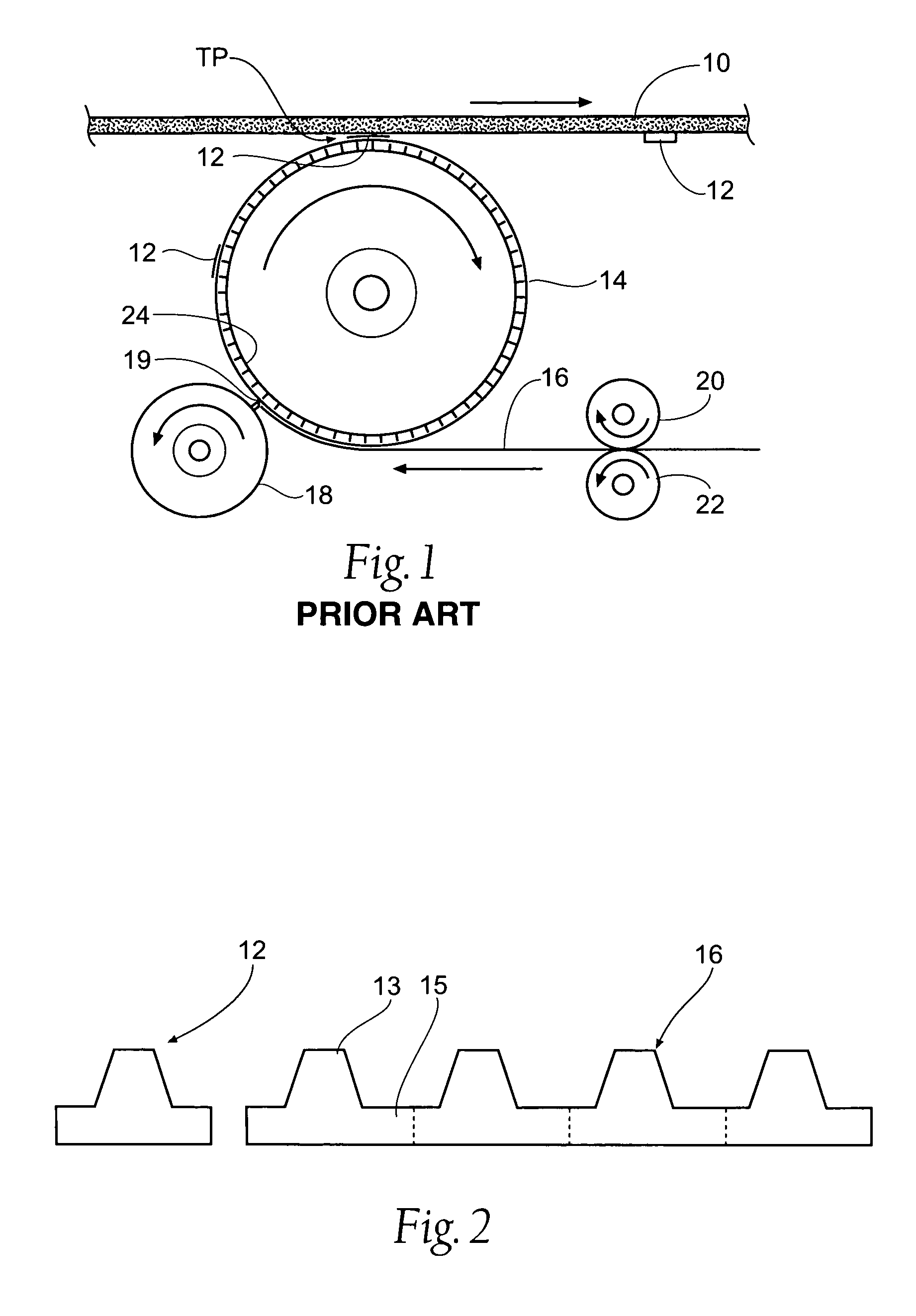
[0022]Referring to the drawings there is seen in FIG. 1 a diagrammatic illustration of a prior art process for applying tabs to webs in a diaper making process. The present invention can use this prior art method of affixing the ears 12 to the web 10, with a different anvil, the new anvil 114 described below. Web 10 is a composite material used in formation of diapers which is generally formed of various layers of material such as plastic back sheets, absorbent pads and nonwoven topsheets. A series of ears 12 are applied to web 10. In the illustrated process a rotatable vacuum anvil 14 is used to ...


PUM

PropertyMeasurementUnit
radiusaaaaaaaaaa
speedaaaaaaaaaa
surface speedaaaaaaaaaa

Abstract

This invention proposes a new, improved method and apparatus for applying web segments to a traveling web. These web segments, sometimes called ears or wings, may be asymmetrical or otherwise incompatible with the usual slip-and-cut method. The asymmetrical shape may have differing web tensions which can cause the web segments to be improperly engaged with the vacuum holes on an anvil roll. The present invention utilizes both circumferential rows of vacuum holes and an additional pattern of ear retaining vacuum holes. The circumferential rows of vacuum holes are activated consecutively by vacuum commutation, however, the pattern of ear retaining vacuum holes are activated simultaneously to counter the effects of differing web tensions on the ear portions.

Description

BACKGROUND OF THE INVENTION[0001]The present invention relates to disposable hygiene products and more specifically, to methods and apparatuses for processing disposable hygiene products. More specifically, the invention relates to cutting and applying segments of one web to attach to a disposable hygiene product. Various types of automatic manufacturing equipment have been developed which produce the desired results with a variety of materials and configurations.[0002]When manufacturing hygiene products, such as baby diapers, adult diapers, disposable undergarments, incontinence devices, sanitary napkins and the like, a common method of applying discrete pieces of one web to another is by use of a slip-and-cut applicator. A slip-and-cut applicator is typically comprised of a cylindrical rotating vacuum anvil, a rotating knife roll, and a transfer device. In typical applications, an incoming web is fed at a relatively low speed along the vacuum face of the rotating anvil, which is m...

Claims


Application Information

Patent Timeline
Patent Type & Authority Patents(United States)
IPC IPC(8): B32B37/00
CPCA61F13/15699B65H20/12B65H39/14B65H2406/3612Y10T156/1322Y10T156/1317Y10T156/1052Y10T156/1077B65H2801/57
Inventor MEYER, THOMAS C.
Owner CURT G JOA
Why Eureka
Try Eureka